


News & Exhibitions
Latest Factory Updates, Industry Trends & Global Exhibition Information
How to troubleshoot inaccurate hole placement on a furniture side drilling machine
When holes are consistently out of position on a side drilling machine for furniture, start by identifying the pattern of the error. A constant offset often points to a reference or setup problem; an error that grows along the panel suggests a scale, drive, or alignment issue. Random errors call for closer attention to clamping, panel movement, and inconsistent sensing.
Before changing calibration values, measure a known panel against the drawing, record where each hole is wrong, and check whether the same error appears on repeated cycles. This prevents a temporary symptom from being corrected with a permanent offset.
Start with a repeatable measurement
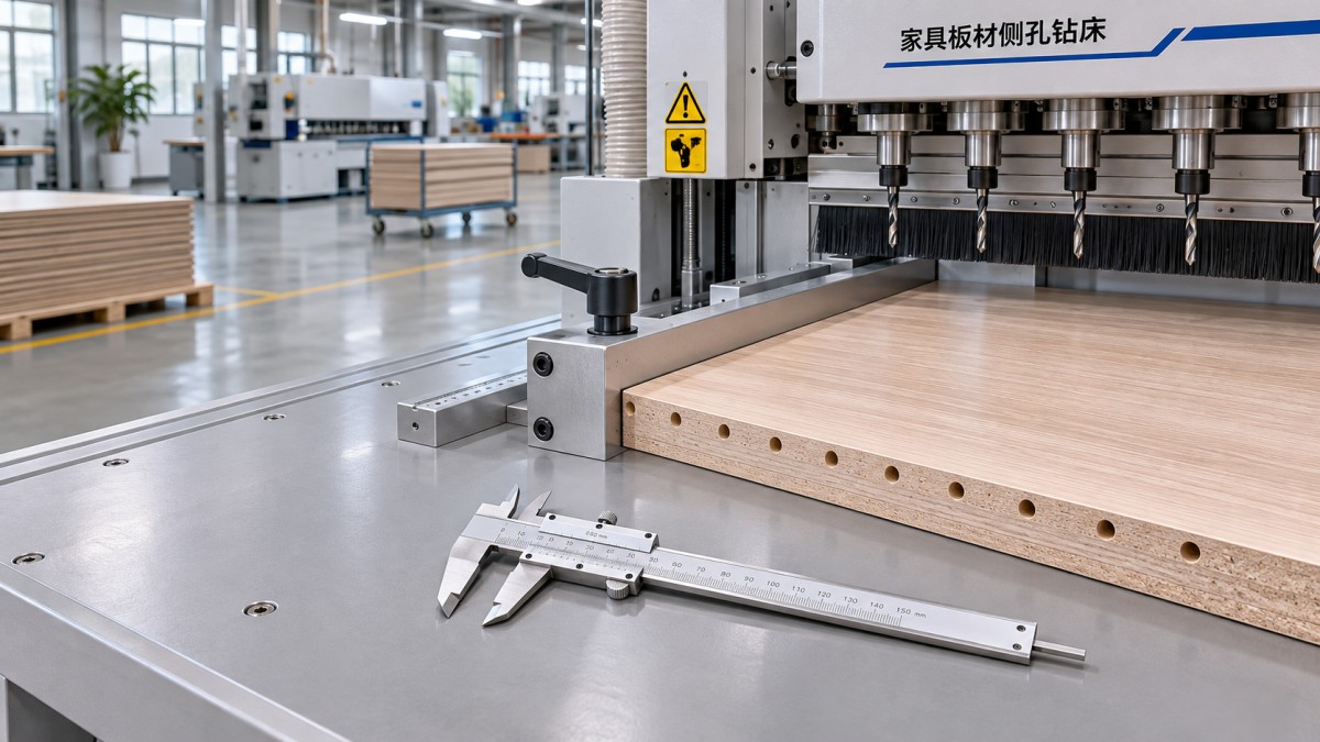
Choose a flat, representative panel with clean edges and known dimensions. Use the same reference edges specified in the job drawing or program, and mark the face and end that should contact the machine’s locating surfaces. Check that the part has been loaded in the intended orientation.
Measure hole positions from the designated reference edge to the hole center, not just from one hole to the next. A panel can have correct hole spacing while the whole pattern is shifted. Measure both the distance along the panel and the height of the holes in the edge. Where possible, use a suitable hole-center gauge or measuring fixture; measuring to the edge of a damaged or oversized hole can produce a misleading result.
Record the programmed positions, measured positions, panel dimensions, material, drilling head, and loading orientation. Run several test panels under the same conditions. Compare the results before adjusting anything:
- The same offset on every hole: Check the reference point, locating stop, work offset, and program origin.
- Error increases with distance from the reference: Check axis travel, drive components, positioning scale, and panel-to-axis alignment.
- Hole positions vary from panel to panel: Check clamping, panel seating, sensor operation, and mechanical looseness.
- Only one spindle or hole in a group is wrong: Inspect that tool, its holder, and any spindle-specific offset or mechanical play.
- Position is correct along the panel but wrong in height: Check panel thickness, support surfaces, drilling-head height, and the face used as the vertical reference.
These patterns narrow the search; they do not prove a single cause. A machine may also have more than one fault, especially after a collision or a change in production setup.
Check the panel before recalibrating the machine
A side drilling program assumes the panel reaches the same reference surfaces on every cycle. Dust on a stop, a chip under the panel, damaged edge banding, or a bowed workpiece can change the actual starting position even when the CNC coordinates are correct.
Inspect the panel edges for squareness and damage. Confirm that the dimensions match the program and that the correct face is against the support. With edge-banded parts, determine whether the program references the finished edge or the unbanded panel edge. A mismatch can shift a hole pattern even though the machine repeats accurately.
For a batch problem, compare a defective part with a known-good part from the same job. If only panels from one cutting batch are affected, measure their length, width, squareness, and edge condition before changing drilling settings. If panels of different sizes show different errors, look for an incorrect part dimension, loading reference, or mirroring setting in the job data.
Upstream cutting accuracy matters because the drill locates from the physical panel, not the drawing. For example, the CNC BEAM SAW ZD330F is an upstream CNC cutting machine for panel materials, with a stated cutting accuracy of ±0.1 mm. It is not a side drilling machine, and its specification does not establish the accuracy of finished holes. Cutting, handling, edge banding, and drilling references must still be checked together.
Verify stops, sensors, and the machine reference
Inspect fixed stops and locating surfaces for wear, movement, impact damage, and accumulated debris. After cleaning, seat the panel against the intended stops and check for gaps. A stop that looks correctly positioned can still shift under pressure if its mounting is loose.
On machines that detect the panel with a photoelectric, laser, or contact sensor, examine the sensing face and mounting. Dust, a loose bracket, or a damaged cable can make the detected position inconsistent. Material color, surface finish, edge banding, and panel condition may also affect optical sensing, depending on the sensor. Use the machine’s diagnostic screen and the sensor manufacturer’s procedure to check whether the input changes reliably at the intended position.
If the same pattern is displaced by a similar amount on every test, compare the active work origin and sensor-to-tool offset with the documented setup. Confirm that the correct program, tool, and reference side are selected. Do not assume that a displayed coordinate is the physical hole center: the control may apply machine-specific offsets between the sensor, spindle, and programmed position.
After a sensor or stop has moved, restore its position and follow the manufacturer’s reference or calibration procedure. Record the original values before changing parameters, and adjust only the value associated with the confirmed error. An offset may make one test panel pass while hiding a loose sensor or an incorrectly loaded part.
Rule out movement during clamping and drilling
A panel that seats correctly can still move when the clamps engage or when the drill enters the edge. Look for witness marks, uneven clamp contact, worn pads, and insufficient support near the drilling area. A narrow or short workpiece may need approved supplementary support or a fixture that holds it square without interfering with the tool path.
Inspect the pneumatic system for leaks and unstable pressure, and compare the operating condition with the machine manufacturer’s requirements. Too little clamping force can allow movement; excessive or uneven force can distort a thin panel or push it away from the locating surface. Adjust the setup for the material and panel geometry rather than assuming that more pressure always improves accuracy.
To distinguish loading error from drilling movement, check panel seating before the cycle and inspect the result immediately afterward. Use the machine’s approved setup or diagnostic mode and keep clear of moving parts. Never hold a workpiece by hand during drilling or bypass an interlock to observe it more closely.
Inspect the drill, spindle, and feed conditions
A blunt, chipped, bent, or incorrectly seated drill can wander as it enters the panel, particularly near a laminate surface or an uneven edge. With the machine isolated and motion stopped, inspect the cutting edges, shank, collet or chuck, and tool seating. Clean mating surfaces before reinstalling a tool, and use the correct tooling and tightening procedure for the spindle.
Check whether the affected hole is actually displaced or simply oversized. A worn tool or excessive runout can produce an irregular hole that is difficult to measure accurately. If one spindle in a multi-spindle head is consistently different from the others, compare its tool, holder, mounting, and programmed or mechanical offset with those of the correctly positioned spindles.
Feed rate and spindle speed should suit the tool and material. Excessive feed can deflect the bit or move a poorly supported panel; inappropriate cutting conditions can also worsen edge breakout. Reduce the drilling load only as a controlled diagnostic change, using the tool and machine guidance. If the error disappears, inspect support, tool condition, and clamping as well as the cutting parameters.
Trace progressive errors to the axis and drive
When the position error grows along the length of a panel, plot or record the deviation at several programmed positions. A steadily increasing difference can indicate an axis scaling or transmission problem. Irregular changes may point instead to friction, a loose component, or intermittent motion. Do not correct a progressive error with a single origin offset: that only moves the entire pattern.
Inspect the applicable drive components for looseness, wear, contamination, or damage. Depending on the machine, these may include a belt and pulleys, rack and pinion, ball screw, coupling, linear guide, or encoder feedback components. Check for abnormal resistance or play using the manufacturer’s inspection procedure. A collision or recent service makes disturbed mounting or alignment particularly relevant.
Backlash is another possibility when the final position depends on the direction of travel. Compare positions approached from opposite directions using an approved test procedure and a suitable measuring instrument. A direction-dependent difference can indicate lost motion, but determine its mechanical source before changing compensation settings. Compensation cannot repair a loose coupling or a worn drive.
Axis calibration and mechanical alignment should be carried out by personnel authorized for the machine, using appropriate measuring equipment. Record original settings and test results so that changes can be reversed or traced. Electrical cabinets, servo drives, and moving axes present hazards; isolate energy and follow lockout procedures before mechanical or electrical inspection. Live diagnostics should be performed only under the manufacturer’s safe procedure.
Separate program errors from machine errors
If the machine passes a simple reference test but fails on a production job, examine the job data before adjusting the machine. Check the panel size, hole coordinates, drilling face, part orientation, mirroring, and any allowance for edge banding. Confirm that the drawing and CNC program use the same reference corner.
Pay particular attention to left-hand and right-hand furniture parts. A mirrored panel may require a different reference or transformed coordinates; turning the panel over is not necessarily equivalent to using the correct mirrored program. Compare the displayed tool path or hole list with the drawing before running another part.
If only one job is affected, reproduce it with a clearly marked test panel and a simple hole pattern. If several unrelated jobs show the same physical offset, investigate the machine reference and setup. This comparison helps avoid correcting sound programs to compensate for a machine fault, or changing machine calibration to compensate for a bad program.
Confirm the repair across the working range
After correcting the identified cause, run repeated test panels using the normal loading and clamping method. Measure holes near both ends of the working range, as well as any positions or spindles that previously showed errors. Check hole height and spacing, then assemble or gauge representative mating parts where the job requires it.
Compare the results with the tolerances on the job drawing. A single acceptable hole does not demonstrate that the entire pattern is correct, and one successful cycle does not establish repeatability. If the error remains variable, return to panel seating, sensing, and clamping; if it changes with travel distance, continue investigating the axis and its alignment.
Document the fault pattern, measurements, parts replaced, parameter changes, and final test results. If the cause cannot be isolated without drive calibration, sensor setup data, or machine-specific procedures, provide those records to the equipment supplier along with the model, control version, and affected program. The measurement history gives technical support a useful starting point and reduces unnecessary adjustments.
Send Your Inquiry
We welcome your cooperation and we will develop with you.