


News & Exhibitions
Latest Factory Updates, Industry Trends & Global Exhibition Information
How to isolate the cause of inaccurate cuts in woodworking machines
How to Isolate the Cause of Inaccurate Cuts in Woodworking Machines
Inaccurate cuts rarely come from a single obvious fault. A panel saw may cut square on one side of a sheet but drift at the end. A sliding table saw may produce clean parts that do not match the programmed dimension. An edge-banding line may appear to have a trimming problem when the real issue began with panel squareness at the saw. In each case, replacing parts before identifying the source can create more downtime, more adjustment work, and no lasting correction.
Effective Woodworking Machine Troubleshooting starts by separating the symptom from the cause. The goal is not simply to find a component that looks worn; it is to determine whether the error is generated by the cutting tool, spindle or arbor, guide system, workholding method, table geometry, material condition, or control settings. A disciplined sequence matters because several small deviations can combine into a visible cutting error.
Before adjustment begins, record what is actually happening. Is the error consistent or intermittent? Does it occur on crosscuts, rip cuts, mitres, or only one workpiece length? Does it become worse after the machine warms up? These observations narrow the investigation far more effectively than beginning with a general alignment check.
Define the Cut Error Before Touching the Machine
“Inaccurate” can mean several different things, and each pattern points toward a different group of causes. A dimensional error is not necessarily an angular error. Tear-out is not evidence that a fence is out of parallel. A burned edge may result from blade condition, feed pressure, material stress, or blade-to-fence relationship.
Begin with a controlled test piece. Use material that is reasonably flat, stable, and free from obvious damage. Mark its reference face and reference edge. Make repeated cuts without changing the setup, then measure at more than one location. For squareness, compare the two ends of a test part or use a reliable square suitable for the machine’s expected tolerance. For dimensional repeatability, measure a series of parts rather than relying on one cut.
This initial classification prevents a common mistake: correcting the machine for an error caused by the cutting process. If a saw produces the correct size but leaves a scorched or fuzzy edge, changing the digital stop calibration will not solve the problem.
Rule Out the Blade and Tooling Assembly
The blade is often blamed first, sometimes correctly. A dull blade raises cutting force and can deflect under load. Resin buildup changes the cutting action and may increase heat. Damaged teeth, incorrect tooth geometry for the material, or an unsuitable kerf can all affect edge quality and tracking. However, a blade should be evaluated as an assembly, not only as a consumable.
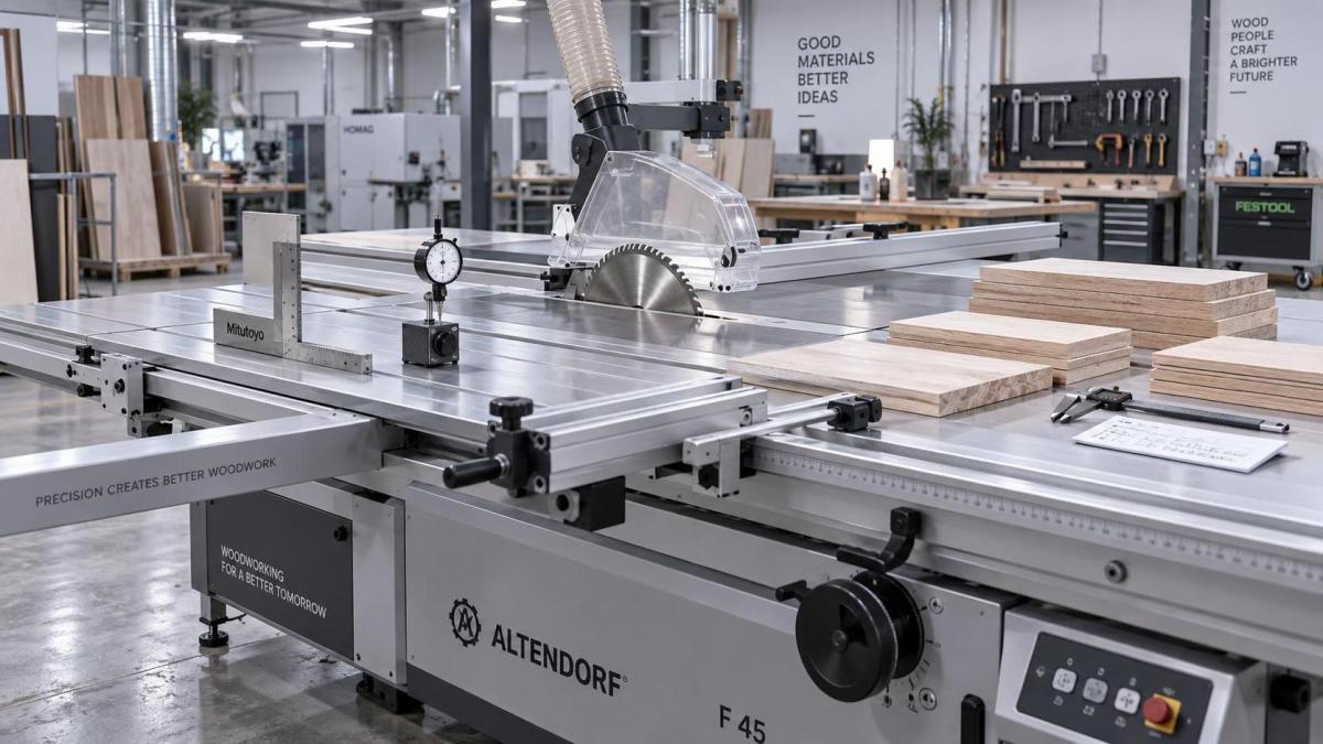
With power isolated in accordance with site safety procedures, inspect the blade body, teeth, bore, flange surfaces, and arbor seating area. Dust, resin, a damaged flange, or a foreign particle trapped between the blade and flange can introduce lateral runout. A blade that appears to wobble may not be bent at all; it may simply be seated against an unclean mounting surface.
If suitable measuring equipment is available, check runout at the arbor and then at the mounted blade. The purpose is comparison rather than reliance on a universal number. If the arbor reading is stable but the blade reading changes significantly after mounting, the blade, flange, or seating surfaces deserve attention. If both readings show similar movement, investigate the spindle or arbor itself.
Do not overlook blade tension and cutting load. A blade can seem acceptable during a no-load rotation check yet deflect during a heavy rip cut. This is especially relevant when cutting dense board, solid timber with internal stress, laminated materials, or material thickness close to the machine’s practical capacity. A controlled comparison using a known-good blade is often faster than extended debate about tooth condition.
Check the Machine Geometry in the Right Order
Once tooling is excluded or corrected, move outward from the cutting axis. On a fixed-table saw, the critical relationship is generally blade plane to rip fence. On a sliding table saw, the relationships between blade, sliding carriage, crosscut fence, and stop system all matter. CNC routers and machining centres add gantry squareness, spindle condition, vacuum holding, and axis positioning to the investigation.
Avoid adjusting every alignment point at once. Establish one stable reference and work from it. For example, confirm that the blade is mounted correctly and that the arbor is sound before assessing fence parallelism. Confirm carriage travel before resetting a crosscut fence. If the reference itself is wrong, later adjustments can hide the original problem and make future servicing harder.
Rip Fence and Guide System
A fence that is not secure, straight, or correctly positioned relative to the blade can create inaccurate width and poor cut quality. The practical symptom depends on the direction of error. If the workpiece is squeezed between the fence and the rear of the blade, heat marks, noise, and kickback risk may increase. If the workpiece moves away from the intended path, the result may be variable width rather than a clean, repeatable error.
Check for looseness in the locking mechanism, dirt on the guide rail, damaged contact pads, and play that appears only when pressure is applied to the fence end. A fence can look correct when measured at rest but shift during a full-size panel cut. That distinction is why a static measurement should be followed by a practical cutting test.
Sliding Table, Crosscut Fence, and Stops
On sliding-table equipment, carriage condition is central to cut squareness. Debris in the guideway, bearing wear, incorrect carriage adjustment, or damage from handling large panels can create movement that is difficult to see but easy to measure on finished work. Check travel across the full stroke rather than at one point. Some faults appear only near the ends of travel, where load and leverage change.
The crosscut fence should then be checked independently. A fence that is straight but not square to carriage travel creates a consistent angular error. A fence with a loose pivot, stop, or extension may create inconsistent results. Long workpieces make these issues more visible because a small angular deviation at the fence becomes a larger dimensional difference at the far end.
Where a digital readout or powered stop is involved, distinguish mechanical positioning from displayed positioning. If the stop reaches the same physical point every time but the display is wrong, recalibration may be appropriate. If the stop fails to reach the same point repeatedly, calibration alone is not the answer; inspect the drive, coupling, encoder feedback, limit reference, and mechanical obstruction.
Look at the Workpiece as Part of the System
Machines do not cut ideal material. A bowed board can rock against a table. A warped panel can shift against a fence. Internal stress in solid wood may release during ripping and cause the kerf to close or open behind the blade. Laminated boards may have damaged edges or uneven surfaces that make repeatable referencing difficult.
When an error appears only on certain materials, compare the same setup using a flat reference panel. If the machine cuts the reference panel correctly, avoid making alignment changes until material handling has been evaluated. Support rollers, sliding-table support, clamps, pressure devices, vacuum zones, and operator feed technique can all influence the final result.
This is also where process sequence matters. In furniture production, a panel that was cut slightly out of square at the sizing stage can produce misleading faults at drilling, edge-banding, or assembly. Trace the first operation at which the reference edge or dimension was created. Repairing the final machine in the route may only treat the visible consequence.
Separate Mechanical Errors from Settings and Control Errors
Modern woodworking equipment may combine manual adjustments with digital scales, servo stops, PLC-controlled sequences, and CNC programs. This can lead maintenance work in the wrong direction: a dimension mismatch is sometimes treated as a software problem before the mechanical stop is verified, or a real encoder issue is treated as fence misalignment.
A useful isolation method is to compare command, movement, and result. What dimension was entered or selected? Where did the mechanism physically stop? What dimension was actually cut? If the entered value and physical position disagree consistently, inspect calibration, reference offsets, units, and program data. If physical position varies despite identical commands, investigate backlash, belt or rack condition, coupling security, drive tuning, and sensor feedback. If physical position is stable but cut size varies, return to workholding, blade deflection, or material movement.
For CNC operations, confirm the active work offset, tool length data, tool diameter compensation, program revision, and tool path strategy before modifying machine parameters. A wrong tool entry can create a repeatable dimensional fault that looks exactly like axis calibration drift. Conversely, a loose spindle, worn collet, or inadequate clamping can produce inconsistent dimensions that no program edit will correct.
Use a Repeatable Diagnostic Record
Good troubleshooting becomes faster when observations are retained. Record the machine model and configuration, material type and thickness, blade or tool used, cut direction, expected dimension, measured result, and adjustments made. Photographs of the cut edge and measurement setup are useful when remote technical support is needed. They also prevent the next service visit from repeating the same checks without context.
A practical record should include what was ruled out, not only what was found. “Blade replaced, no change,” “fence lock checked under load,” or “error occurs only with bowed panels” gives the next technician a clear path. This approach is particularly valuable where several shifts use the same machine and setup changes occur between production runs.
At Qingdao Zhongding Machinery Co., Ltd., long-term machine support is treated as part of the equipment lifecycle rather than a separate after-sales task. With more than 20 years in woodworking machinery manufacturing and export, the practical lesson is consistent: precision problems are resolved most reliably when technicians receive complete machine information, verify the reference condition, and change one variable at a time. Spare parts availability matters, but correct diagnosis determines whether a replacement part is necessary in the first place.
When Adjustment Should Stop and Escalation Should Begin
Some faults should not be corrected through repeated local adjustment. Escalate the issue when there is evidence of spindle bearing damage, cracked or distorted structural components, recurring electrical positioning faults, abnormal vibration, unexplained movement in a safety-related mechanism, or a sudden change in accuracy after impact or transport. Continued operation may damage tooling, compromise cut quality, or introduce a safety risk.
When requesting technical assistance, provide the test-cut results, measurements, photos or video of the relevant movement, tooling details, and a description of when the fault began. That information allows the service team to distinguish a likely adjustment issue from a component or installation problem. Inaccurate cuts become manageable when the diagnosis follows the cut path—from tool and spindle, through guides and tables, to material support and control logic—rather than relying on trial-and-error adjustment.
Send Your Inquiry
We welcome your cooperation and we will develop with you.