


News & Exhibitions
Latest Factory Updates, Industry Trends & Global Exhibition Information
CNC Panel Drill Hole Misalignment: Checks for Clamps and Sensors
When holes drift out of position on a wood panel cnc drilling machine, start by establishing how the error appears. A complete hole pattern that shifts together points toward a different set of checks than holes that move progressively across the panel. Clamps and sensors deserve early attention when the error varies between otherwise identical panels, appears after a repositioning cycle, or changes with panel thickness.
A sensor showing “on” does not prove that the panel is correctly positioned, and a clamp that closes does not necessarily hold the panel securely during acceleration. Before adjusting either, measure the error against the same reference edges used by the program. That first comparison can prevent a mechanical fault from being hidden by a software offset.
Read the error pattern before changing settings
Use a known program, a suitable test panel and the machine’s specified reference surfaces. Mark the panel’s orientation and measure hole centers from the programmed datum edges, not from an edge that may itself be out of square. Record the direction and approximate size of the error in both axes. If a row of holes is affected, measure holes at both ends of the row as well as near the middle.
Run repeat panels only when it is safe to do so, and keep the material, orientation and program consistent. The pattern of results helps narrow the investigation:
- The whole pattern shifts by a similar amount: Check how the panel seats against its reference, whether a clamp moves it during closing, and whether the relevant positioning sensor detects at the correct point. Program datum and work offset errors can produce a similar result.
- The error changes from panel to panel: Look for inconsistent seating, debris, variable clamp grip, panel movement and unstable sensor signals.
- Holes are correct before a regrip but displaced afterward: Concentrate on the clamp release and regrip sequence, panel support, and any sensor or position confirmation used during that transfer.
- The error grows along the panel: Check for panel rotation or skew as well as feed, axis and measurement issues. A single sensor adjustment is unlikely to explain every progressive error.
- Only one spindle or one group of holes is wrong: Compare the affected drilling unit with the others. Tooling, spindle condition or a programmed tool offset may be more relevant than panel holding.
These are starting points, not fault codes. More than one condition can coexist: a panel that is slightly skewed at loading may also slip when a worn clamp takes over during a regrip.
Check how the clamps locate and hold the panel
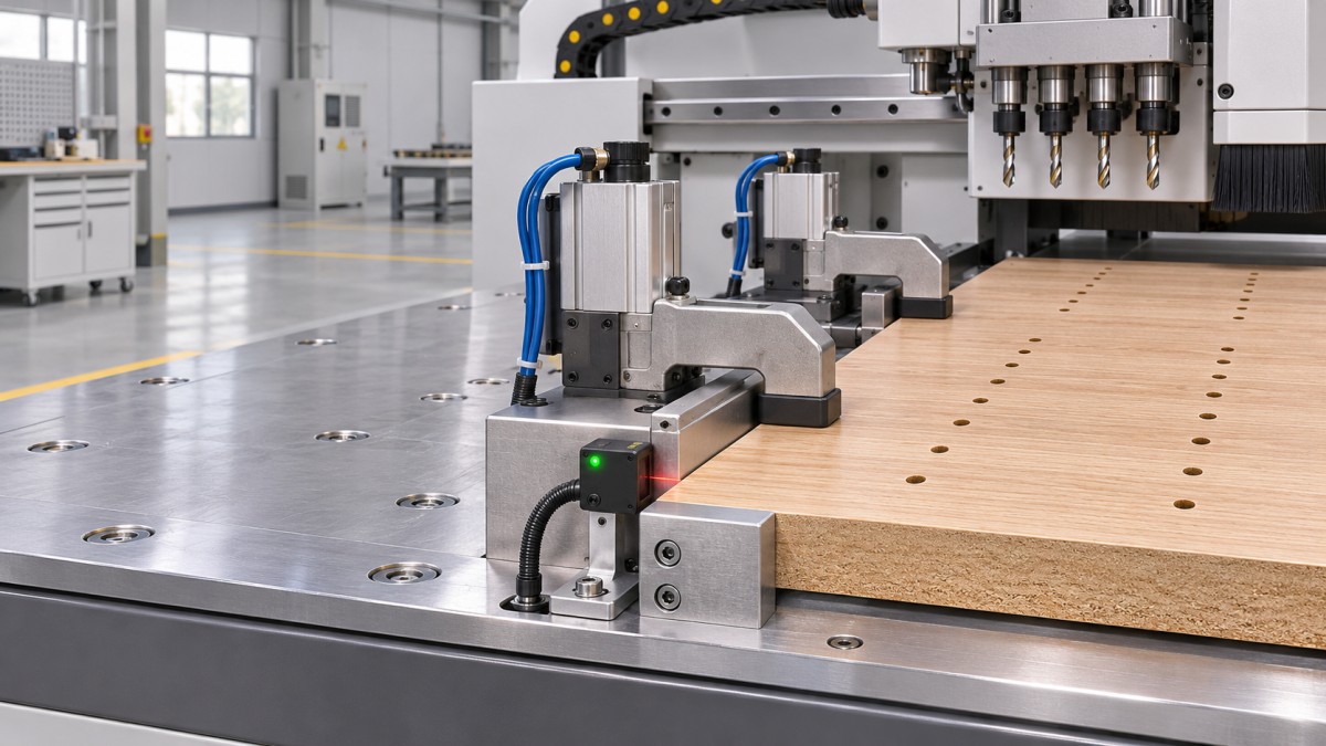
Begin with the path the panel actually follows. It should reach the intended stops or reference surfaces, remain supported, and be held without being pushed away from the datum. Look for chips, edge banding residue, damaged panel edges and buildup on clamp faces or locating surfaces. Even a small obstruction can produce a repeatable offset if every panel seats against it.
Inspect both sides of each clamp contact area. Worn pads, polished surfaces, embedded debris or uneven contact can reduce grip. A damaged jaw may contact only a small part of the panel or pull it sideways as pressure builds. Compare clamp faces across the machine and check whether the affected material has a surface finish or thickness that makes it harder to grip.
With the machine isolated according to its service procedure, check for loose clamp assemblies, damaged guides and excessive play. Inspect cylinders, hoses and fittings for visible damage or leakage. Verify the supplied air or hydraulic pressure against the machine manufacturer’s requirements, measured in the specified operating condition. A pressure indication at the supply does not by itself establish that the clamp applies the intended force at the panel.
Do not raise pressure simply to stop a panel slipping. Excessive force can damage the panel or machine components, while a worn pad, restricted valve or mechanical misalignment remains unresolved. Correct the underlying condition and set pressure within the manufacturer’s specified range.
Where the machine permits a safe observation mode, watch the panel through the complete positioning and drilling sequence from outside the guarded area. Pay particular attention to the moment the clamp closes, the axis accelerates and a clamp releases for regripping. A panel that moves as the jaw closes suggests a different problem from one that stays seated initially and slips during travel.
For machines with multiple clamps, compare their timing and contact. If one jaw closes earlier or reaches the panel differently, the panel may rotate before the remaining clamps hold it. Confirm the sequence using the machine’s service diagnostics and documentation; the expected order depends on the machine design.
When the error appears after a regrip
Mark the point in the program at which the error begins. If holes drilled before the transfer are correct and those after it share a new offset, inspect what happens while one clamp releases and another takes the load. The panel must remain controlled and supported throughout that transition.
Check for clamp interference, insufficient grip by the holding clamp, debris under the panel and wear in the transfer mechanism. Also verify that the machine’s expected clamp positions and confirmation signals match the actual sequence. A regrip fault can originate in a clamp, its control valve, a position sensor or the coordination between them; replacing a sensor without checking panel movement may leave the cause untouched.
Inspect sensors in the context of the movement they confirm
Identify each sensor’s function from the machine documentation before adjusting it. Depending on the design, a sensor may confirm a clamp position, detect a panel edge, identify a stop position or provide an axis reference. These signals are not interchangeable. A clamp-closed signal, for example, may confirm that a mechanism reached a switch point without proving that the panel is firmly held.
Inspect sensor faces and targets for dust, chips, adhesive and damage. Clean them using the manufacturer’s recommended method. Check mounting brackets for looseness or bending, and examine cables and connectors for damage, poor routing or signs of intermittent contact. On optical devices, check the condition and alignment of the emitter, receiver or reflector where fitted. On proximity sensors, inspect the target as well as the sensor face.
Use the controller’s input diagnostics, if available, to compare the displayed state with the actual mechanical position. Move the relevant mechanism only by an approved service method and observe whether the input changes at the expected point. A status light on the sensor is useful, but it should be considered alongside the controller input: a signal can change at the device and still fail to reach the control reliably.
Repeat the check through several permitted cycles. An input that flickers, changes late or behaves differently when a cable moves calls for closer inspection of the sensor, target, wiring and mounting. Follow electrical safety procedures and the machine’s service instructions when testing circuits. Do not reach into moving machinery or defeat guards and interlocks to observe a signal.
Distinguish detection from positioning
A panel-edge sensor may detect a damaged edge, a chip or a surface feature before the panel reaches the intended reference point. Conversely, contamination or poor alignment may delay detection. Either condition can create an apparent positioning error, but the exact effect depends on how the control uses that sensor signal.
Compare the physical panel position with the control’s indicated state and the documented sequence. If the panel is seated correctly but the sensor changes state at the wrong point, inspect the mounting and sensing arrangement. If the signal is correct but the panel is visibly skewed or moving, return to the locating surfaces and clamps.
Adjust sensor position or sensitivity only according to the machine manufacturer’s procedure. Record the original setting first, make one controlled change at a time, and verify the signal throughout the full relevant travel. An adjustment that makes the input switch reliably at one position can create a false confirmation elsewhere if the sensing range or target clearance is wrong.
Separate machine faults from datum and panel problems
Clamp and sensor checks are most useful when the test panel and reference are trustworthy. Confirm that the panel is square enough for the required measurement, that its thickness and dimensions suit the programmed job, and that the operator has loaded it in the intended orientation. A damaged or inconsistent edge can affect both physical seating and measurements taken afterward.
Review the program’s datum, panel dimensions, drilling coordinates and any active work or tool offsets. A consistent shift on every panel can come from those settings even when holding and sensing are sound. Compare the control setup with the drawing and approved program before altering offsets. Changing an offset may make one test panel appear correct while leaving the machine vulnerable to the next regrip or material change.
If the clamps hold consistently, sensor signals are stable and the panel reference is correct, continue with the relevant axis and tooling checks under the manufacturer’s service procedure. A progressive error may involve feed or axis positioning; isolated errors may require inspection of a drilling unit or tool. Avoid treating every inaccurate hole as evidence of a clamp or sensor failure.
Verify the repair under the conditions that exposed it
After correcting the suspected fault, run the same program with the same material and orientation used to establish the original error. Measure from the same datum edges and compare the results with the drawing tolerances. Check the complete affected pattern, including holes on both sides of any regrip, rather than accepting one correctly positioned hole as proof of repair.
Repeat the test enough to assess whether the result is stable. If the complaint involved a particular thickness, panel finish or feed condition, include that condition in the verification. A clean, rigid test panel may hold well even though the production material still slips. Any return to normal operating speed should follow the machine’s approved procedure.
Record the original error pattern, the checks performed, the component or setting corrected and the measurements after repair. If the error remains, that record gives the next technician a reliable starting point and helps distinguish a persistent positioning fault from a new tooling or program issue.
Send Your Inquiry
We welcome your cooperation and we will develop with you.