


News & Exhibitions
Latest Factory Updates, Industry Trends & Global Exhibition Information
Which sliding table saw accessories improve repeatable crosscuts?
The most effective sliding table saw accessories for repeatable crosscuts are a rigid crosscut fence, a flip stop that returns to the same position, hold-down clamps that prevent movement, and support extensions matched to the workpiece. Their priority depends on the error: inconsistent length points toward the stop or workpiece seating; changing squareness suggests fence movement or inadequate support. A digital readout improves setting convenience, but it cannot compensate for mechanical play.
Before selecting an upgrade, separate repeatability from accuracy. A batch can contain identical parts that are all too long because the scale is incorrectly calibrated. Conversely, an average dimension can match the drawing while individual pieces vary. Useful accessory evaluations measure both the spread between cuts and the difference from the target dimension.
Match the accessory to the observed variation
Start with representative material and a stable reference edge. Bowed solid wood, debris against the fence, or a poorly prepared edge introduces variation that an accessory cannot reliably remove. Also establish that the sliding carriage, blade, and existing fence mount are mechanically sound before assessing add-ons.
These patterns guide investigation rather than prove a single cause. A loose fence mounting point, for example, can change both angle and length. Buying a more precise stop before correcting that movement leaves the underlying problem in place.
A crosscut fence must retain its setting under load
A long fence is useful only when its mounting and profile resist the loads created by the intended workpieces. Compare the mounting arrangement, locking surfaces, support points, and telescopic overlap. A substantial extrusion attached through a flexible bracket still allows the reference face to move.
Evaluate rigidity at the positions actually used. An extended fence supporting a long door rail presents a different load from a short fence positioning small furniture components. With the machine safely isolated, apply normal seating pressure near the working end and observe whether the fence or its mounting shifts. Excessive force makes this assessment less representative and risks damaging the assembly.
Angular adjustment should allow controlled corrections without disturbing unrelated settings. Positive locating features are useful when the fence is frequently removed or moved between square and angled work. Their value depends on how consistently the fence returns after the locating surfaces have been cleaned and the lock reapplied.
Confirm squareness through a suitable test cut over a representative width. A small angular error creates a larger end deviation across a wider panel, so a narrow sample gives limited evidence for cabinet-side production. Where a five-cut test is used to amplify angular error, keep the cutting sequence and calculation consistent; it evaluates squareness, not length-stop repeatability.
Flip stops: judge the contact and locking mechanism
A flip stop establishes the length reference for repeated parts. The important details are its resistance to rotation, the stiffness of the contact arm, and the consistency of its lowered position. A stop that visibly settles differently after each lift introduces uncertainty even when its scale remains unchanged.
The contact face must suit the material. A narrow or rounded face can engage a profiled edge inconsistently. A face that allows thin stock to slide beneath it is unsuitable for that thickness. For rough solid wood, prepare the reference end before establishing final length; an irregular end touching the stop at different points defeats repeatable positioning.
Fine adjustment is valuable when a dimension needs correction without repeatedly releasing and sliding the whole stop. Assess whether tightening the main lock moves the setting. This small shift is easy to miss during a demonstration focused only on how smoothly the stop travels.
For telescopic fences, determine which sections carry the measuring scale and the stop. Extension movement, inadequate overlap, or a loose joint can change the effective reference. Calibrate using the installed blade and the intended cutting arrangement, then verify the result with an independent measuring tool.
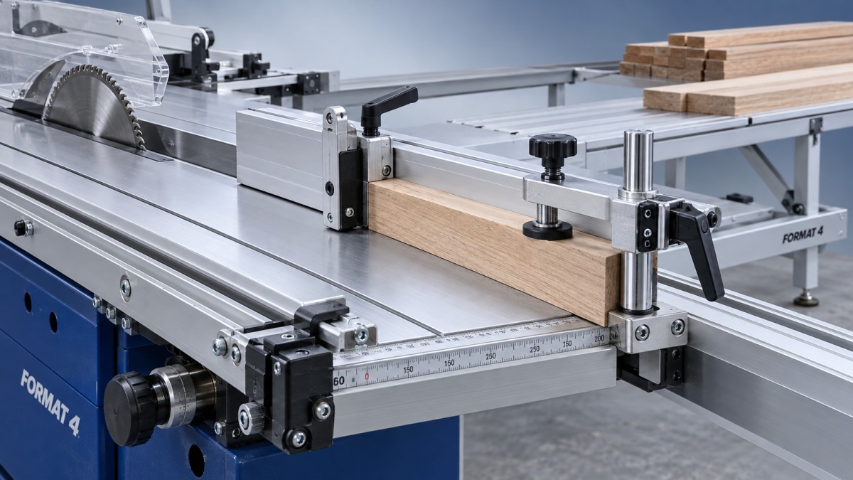
Chip clearance deserves attention around the stop and fence contact surfaces. Packed dust changes where the workpiece seats. A relief feature or accessible contact area simplifies cleaning, but its geometry must still register the smallest intended section securely.
Keep the crosscut stop arrangement consistent with the saw manufacturer’s instructions. Do not use the rip fence as a length stop in a way that traps a crosscut piece between the fence and blade. Where an approved clearance-block arrangement is used, the workpiece must leave that reference before reaching the blade.
Clamps and extensions control different kinds of movement
Hold-down pressure should secure the part without changing its shape
Hold-down clamps reduce lifting and sliding during the cut. Their benefit is strongest with narrow components, slippery surfaces, and parts that are difficult to seat consistently by hand. Clamp travel, throat reach, pad shape, and mounting rigidity all need to match the working section.
Position the pressure over a supported area. Clamping a thin panel across an unsupported gap bends it; releasing the clamp then changes its shape and can expose an apparent machining error. Excessive pressure also marks softer timber or compresses a delicate surface.
Vertical pressure alone does not guarantee contact with the fence and stop. Seat the reference surfaces first, then secure the part while preserving that contact. For pneumatic clamps, stable regulated pressure and compatible air requirements matter. Compare clamp force at the available working pressure rather than assuming that a pneumatic mechanism always holds more consistently.
Confirm clearance through the complete carriage stroke with the machine safely isolated. Clamp bodies, handles, hoses, and mounting brackets must clear the blade, guard, and other machine structures throughout the intended operation.
Support extensions must carry weight without steering the workpiece
Long boards and wide panels place leverage on the crosscut assembly. An outrigger table, extension wing, or suitable support reduces sag and the tendency for the part to rotate away from its reference surfaces. Evaluate the complete support arrangement at the largest intended workpiece size.
Height adjustment is especially important. A support set too high lifts the material away from the carriage or fence reference; one set too low allows sag before it carries meaningful load. Align the support with the machine’s intended working plane and assess its behavior under a representative load.
Freestanding roller supports require care because their orientation and position can encourage sideways movement or lose contact during carriage travel. A support that follows the sliding assembly offers different handling characteristics from a stationary stand. Verify the full travel path, floor stability, and clearance before accepting either arrangement.
Digital scales improve resetting when the mechanics are stable
A digital length display is most useful when production frequently alternates between dimensions. It reduces reliance on reading engraved graduations and makes small setting changes easier to record. Its contribution is smaller in a long batch that already uses a securely locked mechanical stop.
Display resolution is not finished-part accuracy. The measuring system, stop attachment, calibration offset, and workpiece contact all contribute to the result. Request a clear distinction between display increment, positioning accuracy, and demonstrated repeatability under the intended conditions.
Also establish what happens after a power interruption, battery replacement, or movement of a telescopic section. A convenient display becomes a source of scrap if its reference is lost without an obvious indication. The reset and calibration procedure should be practical at the machine.
Prove the setup with cutting and resetting trials
A useful acceptance trial separates variation within a fixed setup from variation introduced by adjustment. Define the permissible length spread and squareness error from the part drawing or assembly requirements before testing. Avoid adopting an accessory’s advertised precision as the acceptance limit for the whole process.
- Prepare representative blanks with consistent reference faces and edges. Include the actual thickness and a demanding production length or width.
- Set the fence and stop, then cut a batch without changing either setting. Measure every part using the same reference and method, recording length and squareness separately.
- Lift and lower the stop between further cuts. This exposes variation associated with its return mechanism.
- Move to another dimension, return to the original setting, and repeat. If fence removal is routine, include a removal and reinstallation trial.
Use measuring equipment capable of distinguishing the permitted variation. Keep seating pressure consistent and record whether the support or clamping arrangement changes between samples. Otherwise, several variables move together and the trial reveals little about the accessory itself.
Compare the results before and after the proposed upgrade under equivalent conditions. Consistent dimensions with a fixed stop, followed by variation after repositioning, justify attention to adjustment and referencing. Variation that persists without resetting points toward seating, rigidity, material condition, or machine movement.
Downstream joinery provides another reason to preserve a clear reference scheme. When crosscut components proceed to a CNC Mortising machine for mortise, slot, or groove machining, establish whether the next fixture locates from a cut end, a long edge, or another datum. Consistent crosscut length does not guarantee consistent joint position if the reference changes between operations.
Choose the upgrade that removes the demonstrated error
For stable square cuts with inconsistent lengths, prioritize stop rigidity, contact geometry, and locking behavior. When large panels lose squareness while small parts cut correctly, investigate support and fence loading before adding a digital scale. For short components that move during cutting, compatible hold-downs offer a more direct intervention than a longer fence.
Compatibility must include mounting dimensions, carriage interfaces, usable cutting capacity, guard clearance, and access for adjustment. Obtain an installation drawing where these details are unclear. An adapter can introduce extra joints and leverage, so assess the assembled installation rather than the accessory alone.
Retain the accepted setup dimensions, calibration method, and trial results with the machine records. Repeat the relevant verification after changing the blade, relocating the fence, or altering the support arrangement. This gives later dimensional changes a known reference and makes it easier to identify which adjustment needs attention.
Send Your Inquiry
We welcome your cooperation and we will develop with you.