


News & Exhibitions
Latest Factory Updates, Industry Trends & Global Exhibition Information
How to secure the saw carriage when packing a beam saw for export
Secure the saw carriage in the transport position specified for the exact beam saw model, using the designated shipping locks and attachment points. The restraint must prevent travel during handling and shipment without bending the carriage, loading the guide rails sideways, or pulling against the drive system. A parked carriage, an engaged servo, or a block placed against the saw blade does not provide a suitable transport restraint.
Before closing the export packaging, establish how carriage loads pass into the machine frame, verify that every locking device is correctly seated, and record the arrangement for removal at the destination. These details matter because a carriage can appear stationary while still having enough clearance to strike a stop repeatedly during transit.
Establish the transport position before moving the carriage
Use the machine’s packing instructions, transport drawing, or original shipping-lock documentation to identify the required carriage location. Do not assume that the normal home position is also the shipping position. Homing establishes a control reference; transport positioning places the assembly where the frame and locking hardware are intended to support it.
The correct location varies with the carriage arrangement and locking system. A machine with a supplied pin-and-bracket lock requires the mating features to align at a particular position. Another design may use removable brackets attached between the carriage structure and the machine bed. Parking at the opposite end simply because access is easier can make the specified restraint impossible to install.
Confirm the machine model, serial number, and any modifications before relying on an older packing photograph. Replacement drives, altered guards, or revised brackets can change the available clearance. If the locking hardware is missing or its mounting points cannot be identified, obtain a model-specific transport arrangement before proceeding. Spare holes in a frame are not evidence that they are suitable restraint points.
Also establish the specified positions of the main blade and scoring unit. Lowering a blade below the table does not necessarily place its lifting mechanism in a secure shipping condition. Follow the instructions for retracting, supporting, or separately locking those movements, and remove blades only where the packing procedure requires it.
Position under control, then isolate stored energy
Complete any powered positioning while the machine remains in its normal operating configuration, with guards and protective devices functioning. Keep the intended parking area clear so that the carriage does not trap loose packing material, tools, or temporary supports as it approaches the transport location.
Once positioned, shut down and isolate the machine using its prescribed energy-isolation procedure. Account for electrical power, pneumatic pressure, and any stored mechanical energy. Where isolation releases a brake or allows an assembly to settle, follow the specified supporting and isolation sequence. Do not loosen a drive coupling, release a brake, or disconnect an air line merely to make the carriage easier to move.
Allow the blade assemblies to stop completely before entering the working area. Access beneath tables or inside guards requires the same isolation discipline as maintenance work. A control-panel stop command does not prevent unexpected movement during restraint installation.
Clean chips and dust from the mounting faces, locking bores, and surrounding frame. Debris trapped beneath a bracket can leave the fasteners apparently tight while preventing full contact. Keep cleaning solvents away from seals and lubricated guide components unless they are approved for that use.
Make the restraint load pass through structural parts
A suitable shipping lock connects the carriage’s designated structural attachment to a designated point on the fixed machine frame. Its geometry must resist the transport movements identified in the packing design. Restraining travel along the beam does not automatically control vertical bounce or movement across the beam; the machine’s guide arrangement and specified locks must address those loads together.
Trace the connection physically: carriage attachment, locking device, frame attachment. Covers, cable-chain supports, lubrication pipes, encoder brackets, and dust-extraction fittings do not become suitable anchoring points because they are close to the carriage. Thin sheet metal can deform while leaving the restraint visibly attached.
Precision components also need protection from restraint forces. Do not loop a strap around a guide rail, ball screw, rack, motor shaft, or blade arbor. A restraint that stops visible travel by bending one of these parts can create alignment or drive problems that only become apparent during recommissioning.
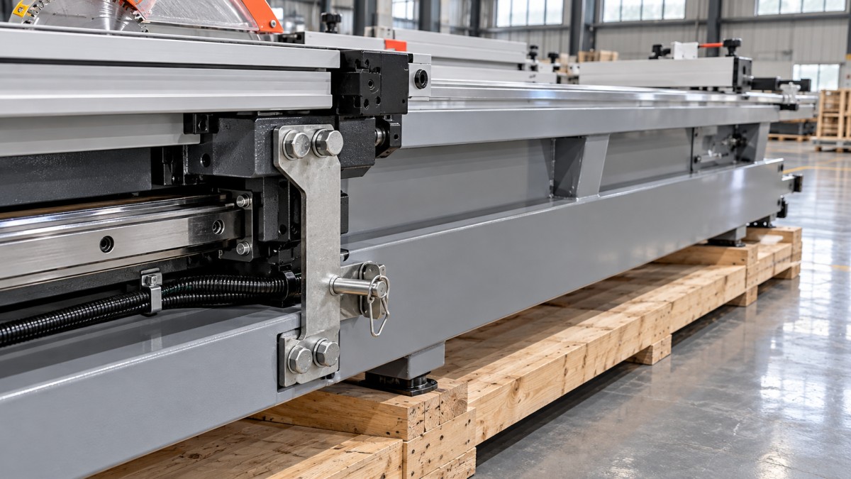
The most useful reference photograph shows both ends of each approved restraint and enough surrounding structure to identify its location. Include a close view of any locking pin, spacer, or bracket orientation that will be difficult to see after the crate panels are fitted.
Fit supplied locks without forcing alignment
Inspect reusable shipping hardware for bent brackets, damaged threads, missing spacers, and distorted pin holes. Match the fastener size, grade, engagement, washers, and tightening method to the transport instructions. A bolt with the correct diameter can still bottom out before clamping the bracket, particularly when an original spacer has been omitted.
Offer up the lock without using its bolts to drag the carriage into position. If the mounting features do not align, investigate the position, bracket orientation, and trapped debris. Forcing the assembly together can preload the guides or distort a bracket before shipment begins.
Install all specified parts before final tightening, following the required sequence and torque. Confirm that pins are fully seated and retained by their intended clips or keepers. Where torque witness marks are used, apply them after tightening; a paint line records relative movement but does not prove that the original tightening was correct.
Use alternative restraints only with an approved arrangement
When original shipping locks are unavailable, a replacement arrangement needs defined attachment points, restraint directions, hardware requirements, and allowable loading. Selecting a strap by its printed capacity alone does not establish that the carriage or frame can accept the force. Strap angle and tension alter both the holding force and the load applied to each attachment.
Approved blocking should contact the intended structural surfaces and remain captured during vibration. Loose wedges can work free, while soft foam compresses and allows travel to develop. Protective pads prevent surface damage only when their material and placement are compatible with the restraint design; they cannot compensate for an unsuitable anchoring point.
Avoid adding tension until every visible gap disappears. Excessive restraint force can twist the carriage or pull it across its guides. The required condition is the specified secure fit, including any designed clearance or preload.
Separate carriage locking from machine tie-down
Beam saw export packaging involves two connected restraint tasks: securing the carriage within the machine and securing the machine to its transport base. A carriage lock does not anchor the machine to the skid. Straps over the machine do not reliably secure the carriage inside it.
Anchor the machine through the base points identified in its packing design. Poor support beneath the frame or uneven tie-down forces can distort the beam and load the carriage guides even when the carriage lock itself is correctly installed. Keep the base support arrangement consistent with the machine’s transport instructions, especially where extensions or supports are removed for shipment.
Review how the packed unit will be lifted. Slings, spreader arrangements, forklift access, and crate panels must leave the carriage restraints undisturbed. A lifting sling bearing against a lock bracket introduces forces that the bracket may not have been designed to carry. Keep carriage-lock attachment points separate from lifting points unless the documentation explicitly assigns both functions.
Do not use cable ties, wiring looms, or cable chains to hold the carriage in place. Secure loose cables and hoses separately, preserving their bend radius and leaving enough slack to avoid tension at connectors. Label disconnected connections so they can be restored without pulling on adjacent equipment.
Verify restraint without stressing the machine
Inspect the completed arrangement while all attachment points remain accessible. Look for full bracket contact, retained pins, correct spacers, adequate fastener engagement, and clearance around rails, sensors, guards, and cables. Confirm that the restraint engages the intended structure on both ends.
If the manufacturer specifies a movement verification, carry it out using the stated method. Do not energize the travel drive against an installed lock, and do not use a pry bar or a forklift to test the restraint. An improvised force test can damage the very components being protected.
Several observations require different responses:
- The bracket is tight, but the carriage still travels: the lock may be incorrectly positioned, incompletely engaged, or missing a required component. Additional bolt torque will not correct the geometry.
- A pin will not enter fully: inspect alignment and the bore for debris or damage. Hammering it into place can conceal a positioning problem and complicate removal.
- A hose or cable becomes taut after locking: its routing or the transport position needs attention before packing continues.
- The carriage shifts after the machine is fixed to the skid: investigate frame support, anchoring, and lock seating before closing the crate.
After the machine is secured to its base and any subsequent handling is complete, inspect accessible locks again. Fresh witness marks, metal dust around an attachment, displaced packing, or a new gap beneath a bracket warrant investigation. Photograph the final arrangement rather than relying only on images taken before base anchoring.
Preserve the lock arrangement through packing and unpacking
Apply the specified corrosion protection to exposed precision surfaces without contaminating braking surfaces, electrical parts, or restraint contact faces that must remain clean. Keep barrier film and wrapping clear of pin retainers and sharp bracket edges. Moisture protection must not hide a displaced lock or become trapped beneath a load-bearing connection.
Place a visible transport-lock notice at the operating controls and another where the crate will first be opened. Identify the installed locks, their locations, and the document containing removal instructions. Labels on removable wrapping alone are easily discarded before the machine reaches the installation area.
Include the final photographs and a record of any separately packed brackets, blades, guards, or supports with the shipment documents. Distinguish carriage shipping hardware from permanent machine fasteners. This prevents a transport bracket from being left installed or a structural component from being removed by mistake.
At the destination, inspect the accessible restraints and surrounding structure before removing them, and record any evidence of movement or impact. Follow the specified sequence for placing and supporting the machine, releasing the locks, restoring removed components, and recommissioning. All transport restraints must be accounted for before powered carriage movement. If a lock is jammed or the carriage binds after release, investigate the cause before attempting a powered cycle.
Send Your Inquiry
We welcome your cooperation and we will develop with you.