


News & Exhibitions
Latest Factory Updates, Industry Trends & Global Exhibition Information
CNC Beam Saw Machine Cutting Capacity: Key Specifications Explained
How much material can a CNC beam saw machine process in a single cycle? The answer depends on more than its maximum cutting length. Cutting height, usable blade projection, feed speed, panel support, and material handling all influence practical throughput and accuracy. A specification sheet may show that a machine can accept a large panel, but that does not necessarily mean it can cut a full stack of those panels at the advertised speed while meeting the required finish.
For technical evaluators, the task is to connect individual ratings to a real cutting pattern: panel size, material, stack height, part dimensions, and the sequence of cuts. The following guide explains the capacity terms that matter and the questions worth asking before comparing machines.
Start with the three dimensions of a cut
A beam saw’s working envelope is usually described through cutting length, cutting height, and a feed-related dimension. These ratings answer different questions and should not be treated as interchangeable.
Terminology varies between manufacturers. A brochure may refer to “cutting width,” “feeding length,” or “pusher stroke” without defining the reference direction. Request a machine layout and working-range drawing, then compare them with the way panels will enter, rotate, and leave the saw.
Cutting height is not the same as blade diameter
Blade diameter is useful information, but it is not a direct statement of stack capacity. Only the portion of the blade that projects above the cutting surface is available to pass through the material. The arbor position, table construction, blade setting, and required clearance all affect the usable projection.
Maximum cutting height is usually the more relevant figure for sizing a stack, but it still needs context. Ask which blade diameter is assumed, whether a scoring blade is used, and whether the rating applies to the material being evaluated. A machine rated for a particular stack height in particleboard should not automatically be expected to deliver the same result in every dense, laminated, or abrasive panel.
Blade condition also changes the picture. Resharpening reduces blade diameter over time, which can reduce projection. If the production plan depends on cutting at the absolute maximum height, establish whether that height remains available throughout the expected blade service range or only with a new blade.
Calculate the stack before discussing output
A simple starting point is:
Nominal stack height = number of panels × nominal panel thickness.
For example, four nominal 18 mm panels make a 72 mm stack. This is only a preliminary calculation: actual thickness variation, panel flatness, protective sheets, and the machine’s stated operating conditions still need to be considered. The practical stack may need to be lower than the published maximum to maintain stable clamping and an acceptable cut.
A taller stack is not always the faster choice. If it requires a slower saw carriage, creates chipping, or causes panels to shift, a smaller stack may produce more acceptable parts over a shift. Confirm the proposed stack height with a representative cutting trial rather than relying on the height rating alone.
Travel speed, feed speed, and production speed
Beam saw specifications often list several speeds. Saw carriage speed describes blade travel during the cutting stroke; pusher speed describes how quickly the panel is positioned. Return speed may be listed separately. These values are important, but none is the same as finished-part output.
The cutting portion of a cycle can be estimated by dividing cutting travel by the selected cutting speed, using consistent units. A complete cycle also includes positioning, clamping, acceleration and deceleration, return travel, and any handling or rotation between cutting stages. The selected cutting speed may be lower than the machine’s maximum because of material density, stack height, blade geometry, or edge-quality requirements.
For a rough production estimate, use the planned cutting program rather than one isolated stroke:
- Define the panel size, material, stack height, and required part sizes.
- Count the cutting strokes and identify where panels or strips must be repositioned or rotated.
- Estimate cutting, return, positioning, and clamping time for each stage.
- Add loading, unloading, inspection, and expected interruptions to establish a realistic operating cycle.
- Divide the number of acceptable parts produced by that cycle time, then validate the estimate in a trial.
This distinction matters when comparing two machines. A higher maximum carriage speed may offer little benefit if the job consists of short cuts, frequent repositioning, or manual handling that dominates the cycle. Conversely, dependable positioning and a suitable loading arrangement can make a substantial difference to daily output.
Power and blade selection shape usable capacity
Main saw motor power is often presented alongside cutting height. It indicates the drive’s potential, not a guarantee that every material can be cut at maximum stack height and speed. The load depends on the material, blade diameter, tooth geometry, tooth condition, cutting speed, and depth of engagement.
When reviewing a proposal, ask for the main saw motor rating and how it is specified, as well as the blade diameter, bore, and recommended tooth configuration for the intended materials. Check whether the motor specification refers to its continuous rating or another duty condition. A direct comparison is only meaningful when the ratings and cutting assumptions are equivalent.
For laminated panels, a scoring blade may be important for the lower surface finish. Its adjustment, blade condition, and alignment with the main blade affect results. The presence of a scoring unit does not by itself guarantee chip-free edges; that outcome also depends on the laminate, blade combination, support, and setup.
Accuracy needs a test method, not just a number
Dimensional accuracy on a specification sheet can be reassuring, but it is useful only when the measurement conditions are clear. Ask whether the figure refers to positioning repeatability, cut-part dimensional tolerance, or another measure. These are related, but they are not equivalent.
Repeatability concerns whether the pusher returns consistently to a position. Finished-part dimensions also depend on blade alignment, kerf compensation, panel movement, squareness, machine setup, and the measurement method. A straight cut is not necessarily square, and a square reference edge is not automatically guaranteed after every handling step.
A practical acceptance test should specify the material, panel and stack dimensions, cutting pattern, blade condition, and points to be measured. Include repeated cuts at the part sizes that matter most to the operation, not just a convenient demonstration size. Measure length and width, check squareness using an agreed method, and inspect both faces for chipping or breakout.
Also establish who supplies the measuring equipment, how the machine is prepared, and which tolerance applies at which stage. A trial with well-supported single panels may be informative, but it does not replace a test of the intended production stack.
Panel support and clamping set practical limits
A large panel may fit the cutting-length specification yet remain difficult to process safely and accurately if it is poorly supported. Front tables, air flotation where fitted, rear support, and the available floor space all influence how easily an operator can move material without dragging or twisting it. Long or flexible panels deserve particular attention during loading and rotation.
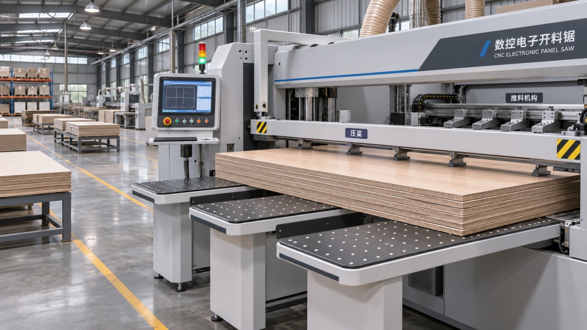
The pressure beam holds the stack during cutting, while rear clamps position material for successive cuts. Their usable ranges affect more than convenience. Confirm clamp opening, positioning, and any restrictions on narrow strips or small remaining pieces. Ask how the machine handles the last cuts in the proposed pattern and whether manual intervention or a different cutting sequence is needed.
Dust extraction is another part of the working envelope. Insufficient extraction can leave chips around the cutting line, affect cleanliness, and complicate maintenance. Obtain the machine supplier’s required extraction airflow, connection sizes, and pressure conditions, then check them against the planned extraction system. Do not size the system from connection diameter alone.
Compare cutting patterns, not brochure maxima
Consider an evaluator choosing a saw for furniture panels with a mixture of wide cabinet components and narrow strips. The maximum panel size establishes the minimum working envelope. The smallest strip and the final cut establish whether the pusher, clamps, and support arrangement suit the pattern. Stack height affects the number of panels processed together, while edge quality may determine the usable blade and cutting speed.
Those requirements can pull in different directions. A machine with ample length and height may still be a poor match if its minimum cut or material handling arrangement makes narrow components awkward. Likewise, a machine that looks smaller on paper may meet the actual production requirement if its usable range, cycle, and handling process fit the job.
For each candidate, request a response to the same set of operating conditions:
- Largest and smallest incoming panel dimensions, including thickness variation.
- Panel material, surface finish, and expected stack configuration.
- Required part dimensions, edge quality, squareness, and dimensional tolerances.
- Representative cutting patterns, including narrow strips and last-cut conditions.
- Available operators, loading method, extraction system, electrical supply, and floor space.
- Expected blade, tooling, maintenance, and spare-parts requirements.
Separate confirmed machine ratings from estimates based on the proposed job. If a supplier quotes output, establish whether it includes loading, unloading, rotation, and downtime. This makes competing figures easier to compare and exposes assumptions before they become installation problems.
From specification review to a defensible selection
The best capacity assessment ends with documented evidence: a working-range drawing, defined cutting conditions, a representative cycle estimate, and an agreed test for finished-part quality. Keep room in the evaluation for blade wear, material variation, maintenance access, and operator handling rather than designing the process around a single maximum value.
Qingdao Zhongding Machinery Co., Ltd. manufactures and exports woodworking machinery and provides technical support, spare parts, and after-sales service. For a machine discussion, sharing panel specifications and representative cutting patterns gives the supplier a clearer basis for assessing the required configuration. It also gives the evaluator a stronger starting point for comparing a CNC beam saw machine against the real demands of production.
Send Your Inquiry
We welcome your cooperation and we will develop with you.