


News & Exhibitions
Latest Factory Updates, Industry Trends & Global Exhibition Information
What acceptance tests should an ATC CNC router manufacturer perform?
Before approving an automatic tool-changing CNC router for shipment, require documented tests of positioning accuracy, repeatability, tool-change reliability, spindle performance, workholding, machining quality, and safety functions. An ATC CNC router manufacturer should demonstrate these against agreed acceptance criteria using the machine configuration, tooling, and materials intended for production—not simply produce one attractive sample.
A demonstration panel can look acceptable while hiding inconsistent tool offsets, weak vacuum retention, or dimensional drift after warm-up. Those problems may appear only during repeated cabinet-part machining or long nested-sheet runs, causing scrap, interrupted cycles, and unsafe operating conditions. Acceptance testing should therefore combine measured machine performance with representative production trials.
Agree on the acceptance protocol before testing starts
The factory acceptance test, or FAT, should be a contractual verification rather than an informal demonstration. Identify the machine by serial number and record its controller version, spindle configuration, tool magazine, vacuum equipment, and installed options. Substituting a different spindle, pump, or control configuration can make earlier results irrelevant.
Define each test’s method, operating conditions, measuring instrument, acceptance limit, and required evidence. Do not accept “high precision” or “smooth operation” as pass criteria. Limits should follow the purchase specification and application requirements; a router producing general cabinet components may need different verification from one machining close-fitting joints.
- Measurement conditions: Record machine leveling, ambient conditions, warm-up procedure, and whether measurements are taken unloaded or during cutting.
- Production conditions: Specify material grade and thickness, cutters, feeds, spindle speeds, cutting depths, and vacuum-zone arrangement.
- Sampling: Agree on measurement locations, repetitions, tool-change cycles, and endurance duration before results are available.
- Failure handling: Define what requires correction, retesting, or shipment suspension, and who authorizes release.
Measuring equipment should have suitable resolution and current calibration evidence. Where a recognized test standard is specified, identify the applicable edition and procedure rather than accepting a general statement that testing follows “international standards.”
Separate axis accuracy from finished-part accuracy
A cut sample does not isolate the machine’s positioning performance. Cutter deflection, material movement, spindle runout, and toolpath settings all affect the result. Request direct axis measurements alongside machining tests so that failures can be traced to their source.
Positioning, repeatability, and reversal
The manufacturer should measure positioning error at multiple locations across each axis’s usable travel, approaching positions from both directions. Repeated returns to the same targets reveal repeatability; differences between opposite approaches reveal reversal effects that a one-direction test can miss. A suitable calibrated laser system or another agreed metrology method can provide this evidence.
Review the largest deviations and their locations, not only an average value. Results near the center of the table do not establish performance at the ends of travel. Record whether compensation was active, and retain the final compensation settings with the machine backup.
Squareness, table reference, and thermal behavior
Check axis squareness, spindle alignment to the working plane, and the relevant table or spoilboard reference surface. A wide surfaced area showing ridges may indicate spindle tram error; a diagonal mismatch in a rectangular test can indicate geometry problems, although cutting forces and workholding must also be excluded.
Repeat selected measurements after the machine reaches normal operating temperature. Cold accuracy alone may not represent a production shift. The report should distinguish geometric table measurements from the flatness achieved after the spoilboard is surfaced.
Make the tool changer prove repeatable seating
The ATC test should exercise every magazine position and the range of approved tool assemblies expected in service. Tool length, diameter, mass, and adjacent-pocket clearance matter: a magazine that handles short cutters correctly may behave differently with longer or larger assemblies.
Run repeated changes as part of a programmed sequence that includes axis movement, spindle starts, machining, and tool-length measurement where fitted. Record failed pickups, incomplete releases, alarms, manual interventions, and cycle times. A successful repeat does not erase an earlier failure; its cause and corrective action should remain in the report.
Tool seating needs its own measurement. Repeatedly remove and reinstall a reference toolholder, then check axial seating or measured tool length and radial runout using an agreed setup. Inconsistent seating can create steps between operations even when the axis measurements pass.
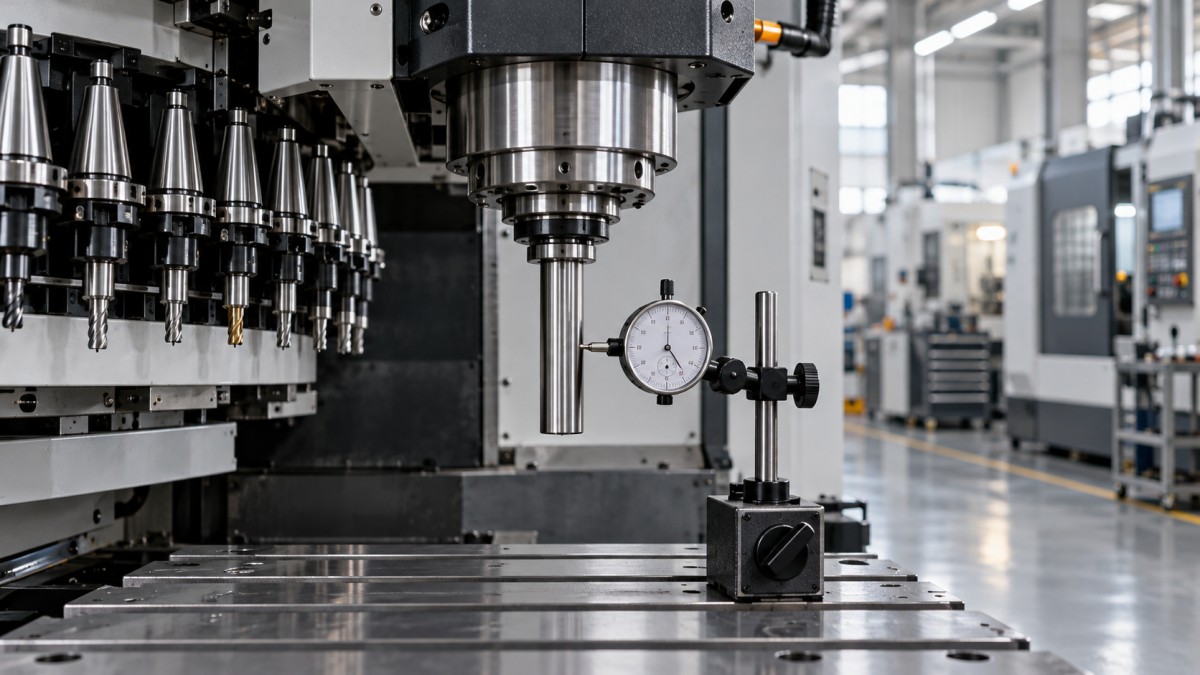
Inspect taper cleanliness, holder condition, pull-stud compatibility where applicable, magazine alignment, and pneumatic pressure during operation. Verify that the controller responds correctly to missing tools, incomplete clamping, and inadequate air pressure using manufacturer-approved procedures. Fault simulation must not involve improvised interference with a moving changer or bypassed safeguards.
Check the spindle under realistic operating conditions
Spindle acceptance should cover warm-up, commanded speed, vibration, abnormal noise, cooling operation, and thermal stability. Measure runout at the spindle interface and with a suitable test arbor where the design allows. Report the measurement position because readings taken farther from the interface are not directly interchangeable with readings taken close to it.
No-load operation is only part of the assessment. Run representative cuts at agreed material-removal conditions and monitor speed stability, drive load, alarms, and temperature trends. Use the spindle manufacturer’s permitted operating envelope; a high maximum speed does not establish adequate torque for every cutter or process.
For a liquid-cooled spindle, verify coolant circulation, cooling-unit operation, and relevant alarms. For an air-cooled arrangement, check airflow and maintenance access. Persistent heating or rising vibration during the trial requires investigation rather than acceptance based solely on a clean surface finish.
Test vacuum holding with the parts most likely to move
Vacuum performance should be assessed at the table during machining, not inferred from pump nameplate data. Effective holding depends on spoilboard permeability, sealing, leakage, active zones, available vacuum flow, and the area remaining beneath each part.
Use representative sheets and include small components, narrow strips, and parts surrounded by previously cut contours. Retention can deteriorate as nesting progresses and more leakage paths open. A test performed only on an intact sheet misses that condition.
- Record vacuum readings at defined locations with the intended zones active.
- Inspect seals, unused-zone isolation, hose connections, and spoilboard preparation.
- Run the agreed cutting sequence and inspect parts for movement, dimensional shifts, or witness marks.
- Verify low-vacuum monitoring and the intended machine response where these functions are supplied.
Parts that lift or shift indicate an unacceptable process condition even if pump readings appear satisfactory. The remedy may involve sealing, revised cutting order, tabs, an onion-skin strategy, or supplementary fixtures. Any such measures must be documented and acceptable for production, not introduced silently to rescue the demonstration.
Use a machining trial that exposes production risks
The cutting test should combine operations that challenge different aspects of the router. A practical panel may include outside profiles, pockets, drilled holes, mating features, and surfaces machined with different tools. Include features at separated table locations to reveal spatial variation.
Use the intended production material where feasible. MDF, plywood, laminated board, and solid wood differ in cutting behavior and holding requirements. An easy-to-machine substitute cannot fully demonstrate performance on the purchased application.
Inspect edge chipping, burning, tear-out, entry marks, and dimensional consistency. Record cutter condition and machining parameters so that defects are not automatically attributed to machine accuracy. Measure parts with suitable instruments and account for material conditioning where moisture or temperature can affect dimensions.
Repeat the panel or selected critical features after sustained operation. Retain identified samples and the corresponding program revision. Cycle-time acceptance should use the complete agreed sequence, including tool changes and normal auxiliary actions, rather than a selectively timed cutting segment.
Verify protective functions before endurance operation
Safety acceptance must be based on the machine’s risk assessment, supplied protective systems, and applicable requirements at the installation destination. A functional demonstration is necessary, but it does not replace required safety validation or conformity documentation.
Qualified personnel should verify emergency-stop devices, guards and interlocks where fitted, travel limits, spindle-start conditions, and prevention of unexpected restart. Test recovery after an emergency stop, power interruption, or relevant utility loss under controlled conditions. Resetting a protective device should not itself initiate hazardous motion.
Check dust-extraction connections and any supplied extraction interlocks with the intended operating arrangement. Confirm that electrical and pneumatic isolation provisions are identifiable and that stored-energy precautions are documented. Do not test a safety function by deliberately creating an uncontrolled collision, tool release, or workpiece-ejection hazard.
Only after protective functions pass should the machine complete a representative endurance run. Log alarms, stoppages, manual adjustments, tool-change faults, thermal trends, and part measurements. Agree on the duration and workload according to the intended duty cycle; an unloaded movement loop provides limited evidence of production readiness.
Release shipment against evidence, then confirm installation
The acceptance package should connect every requirement to a result. Request signed test records, raw measurement data, instrument identification, machining programs, parameter backups, alarm logs, sample measurements, and a register of unresolved deviations. Video can support the record, but it should not replace measurements or conceal interruptions through editing.
Use clear dispositions: accepted, accepted with an explicitly approved deviation, or rejected pending correction. Safety-related failures and failures against essential production requirements should block release. After a repair or parameter change, repeat the failed test and any related checks that the change could affect.
Factory acceptance does not establish performance after transport and installation. Reserve site acceptance checks for leveling, utility quality, extraction, vacuum connections, relevant geometry, safety integration, and a repeat production sample. The purchase agreement should distinguish factory and site responsibilities so that a machine passing in the factory still has to demonstrate the required performance in its installed condition.
Send Your Inquiry
We welcome your cooperation and we will develop with you.