


Choose indexed motion when each surface can be machined with the rotary axis stationary. Choose simultaneous motion when cutting requires coordinated rotary and linear movement.
On a 4 axis ATC CNC router, that decision starts with part geometry. The axis count alone does not establish what the machine can produce.
Indexed machining suits many multi-face woodworking operations, while simultaneous machining supports continuous contours. The distinction affects controller capability, CAM requirements, tooling access, and cycle time.
For technical evaluators, the priority is verifying the complete machining process. This guide explains which motion type fits your parts and which specifications deserve scrutiny.
First, establish what the machine’s fourth axis actually does
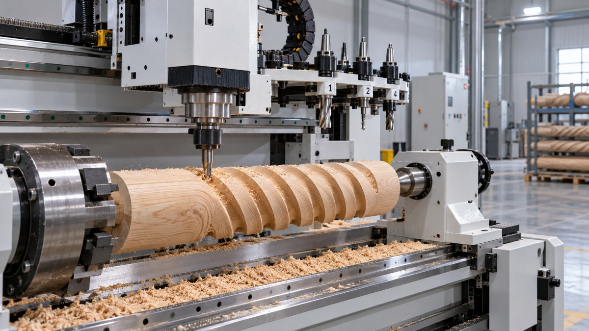
A fourth axis may rotate the workpiece between a chuck and tailstock, or tilt the spindle head. These arrangements provide different access and programming options.
A workpiece rotary axis commonly supports machining around posts, legs, and cylindrical blanks. A tilting head changes the tool’s approach angle relative to the workpiece.
Neither arrangement automatically provides simultaneous machining. A machine may have four controlled axes while permitting the rotary axis to move only between cutting operations.
Ask the supplier to identify the axis arrangement, travel limits, and supported interpolation modes. Request confirmation of how many axes can move together during cutting.
Also verify whether the rotary assembly is standard equipment, an optional attachment, or a substitute for another configuration. Product photographs rarely establish these details reliably.
The automatic tool changer handles tool changes between operations. It does not determine whether rotary motion can be coordinated with linear motion during a cut.
When is indexed motion sufficient for your woodworking parts?
Indexed machining rotates the workpiece or spindle head to a selected angle, then holds that position while the linear axes perform the cutting operation.
For example, a furniture post may need pockets on four faces. The machine can cut one face, index ninety degrees, and repeat the process.
Similar applications include angled drilling, multi-face mortises, flat relief panels around a post, and machining features accessible from a limited number of fixed orientations.
Indexing can reduce manual repositioning and maintain a common setup reference. That benefit depends on reliable workholding, rotary positioning accuracy, and adequate access to each feature.
It is often the practical choice when your existing parts consist mainly of discrete faces. Programming and verification may also fit established three-axis machining workflows.
However, indexed machining does not guarantee seamless blending between orientations. Small positioning errors, tool deflection, or inconsistent stock allowance can leave visible witness lines.
Before accepting indexed motion, examine every critical surface. Confirm that each feature can be completed from an available fixed angle without collisions or unacceptable blending marks.
Which features actually require simultaneous motion?
Simultaneous four-axis machining coordinates rotary motion with selected linear axes during cutting. The changing angular relationship becomes part of the programmed toolpath itself.
Typical candidates include continuous helical grooves, spiral ornamentation, and relief patterns extending around cylindrical workpieces. These features may require rotation throughout the cutting pass.
For such work, repeated indexing can fragment the surface into separate machining zones. Simultaneous movement may produce a more continuous path with fewer transition boundaries.
Nevertheless, a sculpted appearance alone does not prove that simultaneous motion is necessary. Some curved surfaces remain accessible through conventional three-axis cutting at fixed orientations.
Likewise, simultaneous four-axis capability does not make every complex shape machinable. One rotary degree of freedom cannot provide the tool orientations available on a five-axis machine.
Deep undercuts, obstructed features, and changing access requirements can still demand special tooling, another setup, or a different machine architecture. Evaluate accessibility before comparing finish claims.
Ask your CAM programmer to examine representative geometry and identify where rotation must occur during engagement. That analysis provides stronger evidence than an axis-count comparison.
Compare the two modes against actual production requirements
Use the following comparison to screen candidate machines, then validate the result with your own parts. Individual machine design can change the practical outcome.
The comparison should reflect your recurring production mix. An occasional complex feature may justify outsourcing, while frequent rotary contouring may support investing in simultaneous capability.
Separate essential capability from possible future use. A premium feature creates value when it removes a demonstrated production constraint or supports a credible upcoming requirement.
Which controller and CAM specifications must you verify?
Start with written confirmation of simultaneous interpolation for the supplied configuration. A controller family may support options that are absent from the machine’s purchased license.
Confirm which linear axes can participate with the rotary axis and whether travel restrictions apply. Request a demonstration using a program containing continuous rotary cutting.
For indexed work, CAM must support appropriate setups and safe repositioning. For simultaneous work, it must generate toolpaths suited to the actual rotary arrangement.
The postprocessor translates those toolpaths into machine instructions. Verify support for rotary direction, angle conventions, feed commands, retract moves, and any required axis unwinding.
Rotary feed handling deserves particular attention. Depending on the controller and postprocessor, coordinated moves may require inverse-time feed or another supported method of managing feedrate.
For tilting-head configurations, clarify how tool length and pivot geometry are handled. Depending on the architecture, compensation may occur through controller functions, postprocessing, or both.
Do not assume that every four-axis application requires the same compensation features. Ask the supplier to explain the actual method and demonstrate its accuracy.
Include software licenses, postprocessor validation, training, and commissioning in the quotation. These costs can determine whether an apparently complete machine becomes productive after delivery.
Will the mechanics, tooling, and workholding deliver usable results?
Controller capability cannot compensate for insufficient rigidity or unstable workholding. Evaluate the rotary drive, bearings, fixture arrangement, and support method under representative cutting loads.
For indexed cutting, determine how the rotary axis holds position. Some machines use a mechanical clamp or brake; others rely on servo holding torque.
For simultaneous cutting, assess smoothness at low rotational speeds, available torque, backlash, and behavior during direction changes. These characteristics can influence visible surface quality.
Ask how positioning accuracy and repeatability are measured, and distinguish those figures from resolution. Small commanded increments do not establish equally small machining errors.
Long furniture legs and slender posts may deflect even when rotary positioning is accurate. Tailstock alignment, support placement, and cutting strategy therefore deserve attention.
Check the usable machining envelope with the actual chuck, tailstock, toolholder, and dust hood installed. Nominal rotary diameter does not establish collision-free cutting capacity.
Tool reach also matters. Longer tools may access recessed features but increase deflection, while shorter tools may require additional orientations or leave some geometry inaccessible.
Verify automatic tool changes with representative tool lengths and rotary positions. Safe clearances must remain adequate throughout indexing, cutting, retracting, and tool-changing sequences alike.
How should you compare cycle time and total ownership cost?
Simultaneous motion is not inherently faster. For separate faces, indexed machining may allow efficient cutting while avoiding continuous rotary acceleration and more elaborate toolpath calculations.
For wrapped contours, simultaneous motion may reduce repositioning and manual finishing. The advantage depends on geometry, rotary performance, feed limits, and the required surface finish.
Compare complete production cycles, including loading, referencing, tool changes, indexing, machining, unloading, and inspection. Include sanding or blending needed to achieve the specified appearance.
Programming time belongs in the comparison, especially for short batches. A shorter machining cycle may provide limited savings if preparation and verification increase substantially.
Estimate annual value using realistic production volume, labor savings, reduced rework, and added programming costs. Deduct recurring software, maintenance, and training expenses where applicable.
For a preliminary payback calculation, divide the additional installed investment by estimated annual net savings. Use conservative assumptions and avoid counting uncertain future orders.
Ask the supplier about spare parts, technical support, and rotary-drive service procedures. Recovery time after a fault affects operating value alongside the purchase price.
What should a meaningful supplier acceptance test include?
Provide a representative part file, material specification, critical dimensions, and finish expectations. Select features that expose the limitations most relevant to your production requirements.
For indexed machining, include features on multiple faces and check their relative position. Inspect transition areas where separately machined surfaces must meet cleanly together.
For simultaneous machining, include continuous rotary cutting and relevant direction changes. Examine surface consistency, dimensional variation, and any marks associated with rotary motion reversals.
Require the demonstration to use the proposed controller, CAM workflow, postprocessor, tooling, and workholding. Record any equipment or software differences from the quoted configuration.
Measure total cycle time and document manual intervention. A successful cutting demonstration should establish a repeatable workflow that your operators can use after training.
Agree on measurable acceptance criteria before ordering. Include dimensional tolerances, inspection methods, allowable finish defects, and the conditions under which the machine will be tested.
Choose the motion type your parts can justify
Choose indexed motion when your parts resolve into accessible fixed-angle operations and the resulting accuracy, finish, and cycle time meet your documented production requirements.
Choose simultaneous motion when coordinated rotation is necessary for important features, or when a representative machining trial demonstrates a worthwhile improvement in the complete process.
When discussing a 4 axis ATC CNC router with Qingdao Zhongding Machinery, provide drawings, material details, batch sizes, and acceptance criteria for a configuration-specific assessment.
The strongest purchasing decision connects geometry, verified capability, and production economics. Specify the required cutting behavior clearly, then confirm it through a representative acceptance test.