

News & Exhibitions
Latest Factory Updates, Industry Trends & Global Exhibition Information
3-Axis vs. 5-Axis CNC Woodworking Machinery: Which Furniture Parts Need Each?
Choose 3-axis CNC woodworking machinery when the cutting tool can reach the required features from a fixed direction, with manageable repositioning for other faces. Flat cabinet panels, shelves, doors, and many shaped solid-wood components fit this description. Consider 5-axis capability when angled joints, deep contours, or changing surface directions make tool access difficult or require too many separate setups.
A sculpted chair seat does not automatically require five axes, and a rectangular furniture component may still benefit from them if it carries joints at several compound angles. For technical evaluation, the useful starting point is a set of production drawings: which surfaces need machining, how the tool reaches them, and how the part stays securely located throughout the process.
Separate surface shape from tool access
A 3-axis router moves its tool along X, Y, and Z while keeping the spindle orientation fixed during machining. It can cut pockets, profiles, grooves, and three-dimensional reliefs. With suitable cutters and toolpaths, it can also machine many curved surfaces. “Three-dimensional part” and “five-axis requirement” are therefore different judgments.
The limitation appears when the tool needs to approach from another direction. A fixed vertical spindle cannot directly machine every side-facing hole, undercut, or angled mortise. The shop may need to reposition the workpiece, use a dedicated fixture, or fit a compatible aggregate head. Each option has consequences for clearance, accuracy, and handling time.
A 5-axis machine adds two rotary movements through its head, table, or a combination of both. These allow the tool and workpiece to meet at different orientations. However, five available axes do not guarantee that every feature is accessible in one clamping. Rotary travel, spindle-head size, tool length, fixture position, and the machine’s working envelope still restrict access.
It also matters whether the application needs indexed or simultaneous machining. In indexed operation, often called 3+2 machining, the rotary axes position the tool at an angle before cutting with the linear axes. Simultaneous five-axis machining changes orientation during the cut. Many angled furniture joints need only indexed positioning; more demanding surface work may justify continuous movement.
Which furniture parts suit each configuration?
Cabinet panels, shelves, and flat doors
For sheet-based furniture parts, 3-axis machining is a strong starting point. Cutting outlines, routing dadoes and rebates, making hinge recesses, and drilling from the exposed face generally do not require a tilting spindle. A suitable nesting arrangement can combine these operations while keeping panels supported across the table.
Here, productivity may depend more on sheet loading, vacuum hold-down, drilling equipment, tool changes, and unloading than on axis count. A machine configured for panel processing can be a better production fit than a five-axis machine whose additional movements contribute little to the actual cutting sequence.
Edge drilling and opposite-face features need separate attention. A basic vertical spindle does not provide horizontal drilling simply because the part is flat. A compatible drilling block, aggregate, second setup, or separate operation may cover the requirement. Compare the complete process before assigning these parts to a machine category.
Decorative panels, mouldings, and contoured doors
Raised profiles, carved decoration, and shallow reliefs are often suitable for three axes. The tool can follow a changing Z height while retaining its vertical orientation. Surface quality depends on cutter geometry, stepover, grain direction, tool condition, and workpiece stability, as well as machine performance.
Five-axis capability becomes more relevant when deep details create clearance problems, sidewalls obstruct the toolholder, or the design includes features beneath an overhanging surface. Tilting may improve access or allow a shorter cutter. It cannot guarantee access to every recess, and some details may still require special tooling or a different manufacturing method.
Sculpted chair seats
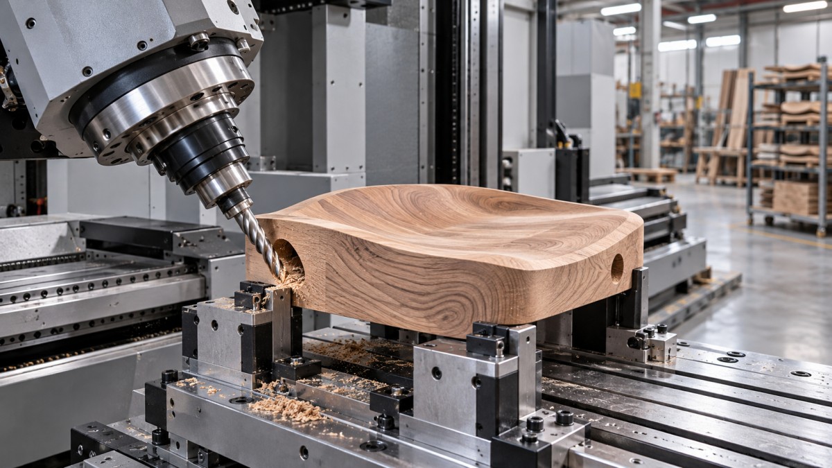
An open, bowl-shaped seat surface can often be rough-machined and finished on a 3-axis router. A ball-nose cutter can follow the contour without the spindle changing angle. If the underside also needs machining, a locating fixture can support a second setup.
The case for five axes strengthens when the seat has steep transitions, deep side contours, or leg and backrest connections entering at different angles. Combining these features in fewer setups may improve their positional relationship and reduce handling. Whether that gain justifies the machine depends on how frequently those features occur across the product range.
Surface finishing deserves a separate trial. Tilting the tool can move the cutting contact away from the center of a ball-nose cutter and improve cutting conditions on some surfaces. Wood grain, cutter selection, feed direction, and vibration still influence the result. A five-axis toolpath does not by itself eliminate sanding or tear-out.
Curved backrests and shaped chair frames
A curved backrest may remain within three-axis capability if its machined surfaces are accessible from one direction or through straightforward repositioning. Parts cut from curved blanks or laminated assemblies should be assessed in their actual machining orientation, including the support needed beneath them.
Compound curvature, side-facing joints, and features distributed around a narrow frame can make five axes more valuable. The machine may reach several joint directions while the part remains on one fixture. This is particularly useful when the relationship between those joints determines how the chair assembles.
Long, slender components introduce another constraint: they can deflect under cutting forces. Additional axes do not compensate for weak support. A fixture that exposes every face but leaves a backrest vibrating may produce worse results than a carefully supported process with an extra setup.
Table legs, rails, and angled joinery
Straight rails with pockets and profiles on accessible faces usually suit three-axis machining. Tapered legs may also be practical with dedicated fixtures and planned repositioning. For components dominated by rotational geometry, a lathe or a suitable rotary-axis arrangement may deserve comparison before moving directly to a five-axis machining center.
Angled mortises, splayed leg connections, and joints on several faces make a stronger case for additional orientation. Indexed five-axis machining can position the tool along each joint’s approach direction without a separate angled jig for every feature.
A critical distinction is whether the cutting direction must change during engagement. A mortise cut at a fixed compound angle may need only indexed machining. A continuous contour around a complex frame may require simultaneous movement. That distinction affects control capability, CAM requirements, programming effort, and the supplier’s demonstration task.
Count setups and check what happens between them
The economic value of five axes often comes from reducing repositioning. But setup reduction should be measured against a workable three-axis process, including the fixtures and auxiliary equipment that would actually be used.
For each representative part, list the cutting orientations and the operations between them. Include releasing clamps, clearing chips from locating surfaces, turning the component, seating it against stops, checking its position, and restarting production. Short machining operations can carry substantial handling effort when these steps repeat across a batch.
Every repositioning also creates an opportunity for location error. This matters when a joint on one face must align closely with a feature machined from another. Machining both from a common clamping position can reduce one source of variation, although final accuracy still depends on machine calibration, rotary-axis behavior, tooling, and workholding.
Conversely, a dedicated fixture may make a second setup quick and repeatable. For a stable product family, that can preserve the economic advantage of three-axis equipment. A shop producing many changing chair designs may place greater value on programmable orientation because it reduces the number of specialized fixtures needed.
Check accessibility with the fixture included in the model. A clamp that works well beneath a vertical spindle may obstruct a tilted head. The component’s underside remains inaccessible wherever it contacts the support, so “one setup” must be demonstrated against the complete part drawing.
Compare finished-part throughput and cost
Spindle cutting time alone is a weak basis for this decision. A useful comparison covers loading, locating, machining, repositioning, inspection, unloading, and any remaining manual work. It should also account for programming and fixture preparation across the expected batch size.
Five-axis machining may shorten handling while adding toolpath calculation, collision checking, or more cautious movements around clamps. A three-axis machine may complete simple panel operations efficiently while requiring extra labor for complex solid-wood components. The balance changes with the part mix.
Evaluate these cost drivers together:
- Batch size and repeat frequency: Repeated batches can spread dedicated fixture and programming costs across more parts. Frequent design changes increase the value of flexible orientation.
- Manual work after machining: Include drilling, trimming, fitting, and sanding that remain necessary for an acceptable component.
- Programming and proving: Confirm that the team can generate reliable toolpaths and verify them for the proposed machine configuration.
- Workholding and tooling: Include fixtures, aggregates, holders, cutter reach, and tool changes required by each route.
- Production capacity: Check whether complex chair components would occupy a machine needed for high-volume panel work.
A mixed production strategy may be appropriate. Panel work can remain on equipment configured for nesting and drilling, while complex solid-wood parts go to a machine with greater orientation capability. Assigning every component to the most flexible machine can consume capacity without creating equivalent value.
Use a representative part trial to settle the decision
Ask for a machining trial based on production drawings and actual material. Select parts that represent both routine work and the geometry driving the investment: for example, a typical panel, a contoured seat, and a frame component with compound-angle joints. A visually impressive carving may reveal little about the shop’s main production constraints.
The trial should establish the proposed fixture, tool list, machining orientations, and remaining operations. Require clarity on whether the demonstrated process uses simultaneous five-axis movement, indexed positioning, aggregates, or manual repositioning. These approaches can all be valid, but they carry different operating requirements.
For the more complex components, examine:
- Whether the spindle head and toolholder clear the workpiece and clamps throughout the cycle.
- Whether joint positions remain consistent after unclamping and reclamping.
- Whether cutting leaves tear-out, vibration marks, or difficult finishing areas.
- Whether the completed joints assemble correctly without unplanned hand fitting.
- Whether the quoted cycle includes routine loading, repositioning, and tool changes.
The CAM system and postprocessor also need to match the machine’s actual kinematics. For five-axis work, verify how tool-center-point control, machine simulation, rotary limits, and collision checking are handled in the proposed configuration. These capabilities affect how confidently a program moves from the screen to the machine.
Choose three axes when the required surfaces are accessible and the remaining setups are economical, stable, and repeatable. Choose five when changing tool orientation resolves recurring access problems or removes enough handling and fixture complexity to justify the additional investment. The strongest evidence is a complete route from blank to acceptable furniture component, with the difficult joints and finishing work included.
Send Your Inquiry
We welcome your cooperation and we will develop with you.