


News & Exhibitions
Latest Factory Updates, Industry Trends & Global Exhibition Information
How to Size a CNC Bandsawing and Drilling Line for Structural Steel Work
A CNC bandsawing and drilling line should be sized from the production constraint, not from the largest steel member shown on a drawing. A line that can physically accept an oversized H-beam but cannot maintain the required hole pattern accuracy, material flow, or shift output will still create schedule risk. Conversely, specifying maximum spindle count and the widest possible infeed system for a project dominated by short channels and light sections can tie up capital while making changeovers and handling less efficient.
The practical sizing question is: what mix of structural members must move from raw stock to correctly drilled, cut, and identified parts within the available production window? Answering it requires more than comparing a machine’s listed beam width, saw motor power, or drilling diameter. Profile geometry, hole locations, lot sizes, incoming material condition, downstream assembly capacity, and the longest expected member all affect the required configuration.
Begin with the work package, not the machine catalogue
The most reliable input is a representative set of fabrication drawings or a digital bill of materials covering the expected work mix. This should be separated by profile family: H/I beams, channels, angles, rectangular hollow sections, square hollow sections, flat bars, and built-up members where applicable. A single “maximum section size” is not enough because a line may process a 600 mm-deep beam effectively while being unsuitable for narrow angles that require different clamping, datum control, or hole orientation.
For each profile family, establish five operating facts:
- section dimensions and unit weight;
- stock lengths received from the mill or supplier;
- finished part lengths, including the frequency of short pieces;
- hole diameter, quantity, spacing, and flange/web location; and
- cut type, including square cuts, mitres, copes, or marks needed for fit-up.
These inputs reveal whether a CNC bandsawing and drilling line is the right primary process or whether some work should remain on a separate angle line, plate processor, coping machine, or manual preparation station. Trying to force every item through one line can reduce handling steps, but it may also lower overall throughput when a minority of awkward profiles monopolizes the main machine.
Part length distribution deserves particular attention. Long beams drive infeed and outfeed roller-table length, while short finished parts affect discharge control. If a 12 m stock beam is cut into many short components, the line needs a practical method to separate, identify, and route pieces without creating a pile-up at the outfeed. The saw cycle may be fast, but production slows if operators must repeatedly stop the line to recover short offcuts or sort mixed parts.
Define the usable processing envelope
Machine capacity should be checked as a usable envelope rather than a single headline figure. The envelope includes the maximum and minimum width, height, and weight of the profiles that can be clamped, positioned, drilled, and cut. The minimum values are as important as the maximum. A heavy-duty clamping arrangement designed around wide-flange beams may not securely reference small channels, light angles, or narrow hollow sections without additional fixtures.
For H- and I-sections, verify the following against actual drawings:
- maximum web height and flange width;
- minimum web and flange dimensions that the clamps can hold repeatably;
- maximum member weight per metre that roller conveyors and feed systems can support;
- clearance for holes near flanges, weld seams, ends, and profile transitions; and
- the saw’s ability to achieve required mitre angles at the largest section.
For hollow sections, the question is not merely whether they fit under the drill head. The clamping method must prevent rotation or movement during drilling, particularly when holes are required on multiple faces. A line arranged for three-sided beam drilling may process an RHS efficiently only if its positioning system, spindle travel, and support rollers maintain a stable datum. Where bolt holes must align across opposite faces, any profile movement under clamp load becomes a quality issue rather than a minor operating inconvenience.
Drilling access near member ends is another common sizing gap. Structural drawings often include connection holes close to the end of a beam. The machine’s minimum end-distance capability depends on clamp arrangement, spindle geometry, saw location, and material support. A stated drilling range may not represent the range available when the line must also make a final cut and retain a usable reference point. This detail should be checked with sample programs before equipment is released for manufacture.
Calculate capacity from cycle time, not nominal feed speed
Line capacity is best estimated in parts and holes per shift for the actual production mix. Nominal saw blade speed or rapid positioning speed offers little insight on its own. A processing cycle includes loading, profile identification, positioning, clamping, drilling, saw approach and cut, part discharge, and any operator intervention. Tool changes, chip removal, marking, program changes, and material replenishment also consume time.
A useful planning model starts with the required finished tonnage or part count per shift, then translates it into representative cycle families. For example, one family may be long beams with repeated web holes and few cuts; another may be short connection members with dense flange drilling and frequent cuts. The latter often consumes much more machine time per tonne, even though it uses less steel.
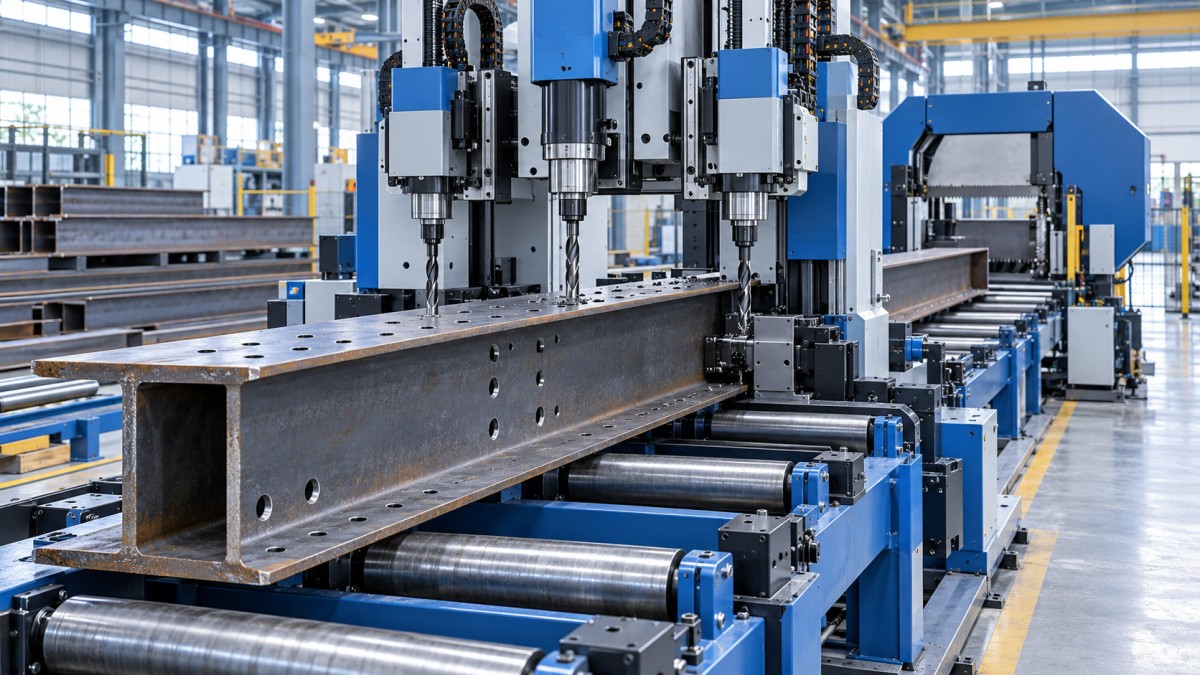
For drilling, estimate the burden using actual hole count and thickness. Hole diameter, material grade, drilling depth, and tool condition affect cycle time. A line with three spindles can drill web and both flanges simultaneously on suitable beam profiles, but this advantage is limited when holes occur on only one face, when different diameters require tool changes, or when the program requires repositioning between groups of holes. More spindles do not automatically mean three times the output.
Saw performance should be evaluated separately. A bandsaw may become the limiting station when members require frequent mitres, when heavy sections demand conservative cutting parameters, or when short part lengths create repeated feed-and-cut cycles. The intended blade type, expected material grades, maximum cross-sectional area, and coolant/chip-management arrangement should be considered together. Selecting a high drilling capacity with an undersized sawing station simply moves the queue to the saw.
For project planning, use a realistic availability allowance rather than assuming every scheduled minute becomes cutting time. The allowance should cover blade and drill changes, routine inspection, stock loading, chip management, minor setup, and recovery from material handling interruptions. The purpose is not to predict an exact output number before installation; it is to identify whether the selected line retains sufficient capacity when the work mix becomes less favourable than the average drawing package.
Choose spindle and tooling capability around hole requirements
The drill specification must match the hole-making method required by the job. Twist drilling, carbide drilling, and other hole-making options have different implications for speed, tooling cost, and material suitability. The decisive factors are hole diameter range, member thickness, required tolerances, steel grade, and the frequency of diameter changes within a program.
Check the maximum diameter not only against the largest bolt hole but also against any required oversized, slotted, or service holes. Standard drilling heads produce round holes; slots may require coordinated drilling operations, milling capability, additional processing, or a different fabrication route. It is risky to assume that a line advertised as CNC-controlled can create every geometry shown in a connection detail.
Tool changer capacity matters when a project contains varied bolt sizes. If the line has limited tool storage, frequent manual tool changes can erode the benefit of automation. However, a very large tool magazine is not automatically necessary for repetitive work using only a few hole diameters. The correct question is whether the available tooling arrangement supports the typical program sequence without disrupting production.
Hole quality depends on more than spindle power. Stable clamping, accurate datum referencing, appropriate feed and speed settings, coolant delivery, chip evacuation, and worn-tool monitoring all affect burr formation, hole position, and tool life. When holes are used in high-strength bolted connections, the fabrication quality plan should define how diameter, location, burr condition, and traceability will be verified against the governing project specification. The line should support this inspection process through reliable part identification and repeatable program control, rather than relying on manual interpretation of marks.
Material handling often determines whether the line delivers its rated value
A processing line is a material-flow system, not just a drill and saw mounted in sequence. Infeed and outfeed configuration should be designed around raw-stock length, bundle condition, member weight, crane coverage, and the way finished parts are transferred to assembly or dispatch.
Incoming steel is frequently supplied in bundles, with mill scale, camber, residual weld distortion, or surface irregularities. The loading system must separate one member at a time without creating unsafe manual handling. If a project uses heavy sections, confirm the conveyor load rating and the ability of transfer arms, cross conveyors, or loading devices to handle the heaviest individual member—not only the average weight.
Space planning needs to include the full stock length ahead of the line, the finished member length beyond it, operator access, tooling service space, chip collection, electrical cabinets, and forklift or crane routes. A line positioned too close to a wall may technically fit in a building but be difficult to maintain or unable to discharge long members safely. The required clear zone changes if the saw makes mitre cuts or if side discharge is used for short parts.
Downstream flow deserves the same attention. Parts should leave the line in a condition that supports the next operation: clearly marked, grouped by assembly or work order, and protected from mix-up. Where marking is required, assess whether the line needs inkjet marking, scribing, stamping, or integration with labels and production software. Marking is not merely an administrative feature; it reduces the risk that drilled members are sent to the wrong assembly bay or installed in the wrong sequence.
Match automation level to production variability
Automation has the greatest value where repeatability and material flow are stable. Automatic loading, automatic tool changing, CNC nesting, part marking, and integrated production data can reduce handling and transcription errors, but only if upstream data is controlled. Poorly structured drawings, inconsistent naming conventions, or late design revisions can turn an automated line into a fast way of producing incorrect parts.
Before specifying software integration, establish the source of the approved fabrication data and the revision-control process. If the line receives programs from detailing software, the workflow should identify who releases files, how revisions are withdrawn, how work-in-progress material is segregated, and how operators confirm that the correct program is active. These controls are especially important when similar members differ only in hole spacing or cut angle.
For mixed, low-volume structural work, rapid setup and straightforward manual override can be more valuable than elaborate automation that is rarely used. For repeatable packages with many similar members, automated material handling and digital job queues may justify their complexity. The decision should follow the expected work pattern, not an assumption that more automation always produces lower unit cost.
Allow for installation, utilities, and commissioning risk
The equipment footprint is only one part of implementation. The facility must provide suitable floor conditions, electrical supply, compressed air where required, coolant management, chip disposal, lifting access for installation, and safe access around moving material. Confirm local electrical requirements, guarding expectations, emergency-stop arrangement, and the responsibility for final site acceptance before the line arrives.
Commissioning should be planned as a production-readiness activity rather than a basic power-on event. Acceptance tests should use representative profiles, drilling patterns, section weights, cut angles, and part lengths from the intended work. This is the point to verify positional accuracy, repeatability, saw cut quality, hole quality, marking readability, material feed behaviour, and program transfer. Testing only a simple straight beam with a few web holes does not demonstrate performance on the difficult parts that often determine schedule reliability.
Spare parts and consumables should be considered before the first job is scheduled. Saw blades, drill bits, coolant components, clamps, sensors, and wear parts can stop a line even when the main machine is mechanically sound. Critical spare holdings should reflect lead times, expected consumption, and the consequences of downtime during a constrained fabrication programme.
Size for a credible future workload, not an undefined maximum
Future capacity should be considered where there is a defined likelihood of larger sections, more dense drilling, longer stock, or higher repeat volume. It is sensible to leave room for additional conveyors, tool capacity, loading automation, or software integration if these can be added without rebuilding the installation. It is less sensible to oversize every machine element for hypothetical work that has no credible route to the shop.
A well-sized CNC bandsawing and drilling line has a balanced processing envelope: it accepts the real member range, completes required holes and cuts without avoidable secondary handling, maintains flow through loading and discharge, and has enough usable shift capacity to absorb normal production variation. The right line is therefore not the one with the largest published specifications. It is the one whose clamping, drilling, sawing, handling, data control, and commissioning plan all support the structural steel package that must actually be delivered.
Send Your Inquiry
We welcome your cooperation and we will develop with you.