


News & Exhibitions
Latest Factory Updates, Industry Trends & Global Exhibition Information
Why Does a CNC Panel Saw Chip Laminated Board Edges?
A CNC panel saw can chip laminated board edges when the scoring blade is worn, misaligned, set to the wrong depth, or unsuitable for the main blade. A dull main blade, unstable board support, and inappropriate feed settings can produce similar damage. The location and pattern of the chips provide the first clues: inspect both faces and the full length of the cut before changing settings.
On a production line, a damaged edge may mean rejected components, extra edging work, or a machine stopped while the cause is investigated. The fastest route back to consistent cutting is to establish whether the defect follows the blade, the material, or a particular machine condition, then change one variable at a time.
Start with the damaged edge
Mark the upper and lower faces of a sample before cutting. Label the leading and trailing ends as well, and note the board orientation on the saw. These simple references make it easier to compare defects after an adjustment, especially when a panel is turned over or the cutting direction is not obvious from the finished part.
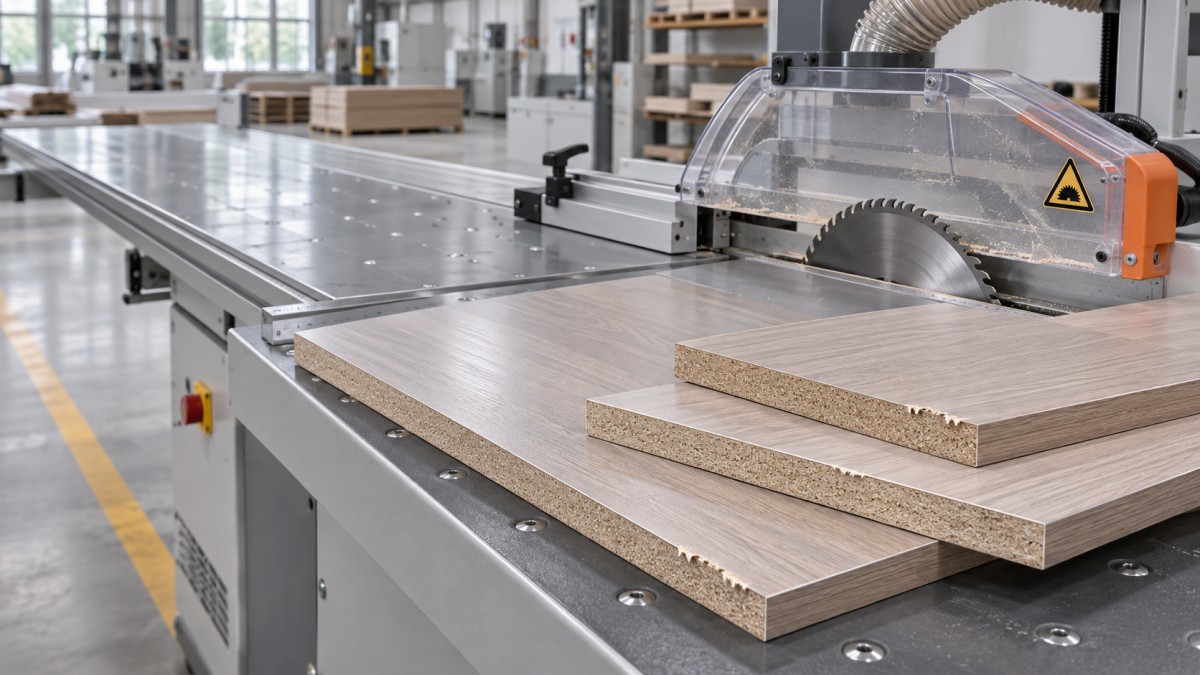
On machines fitted with a scoring unit, the scoring blade normally cuts a shallow groove in the underside laminate ahead of the main blade. It reduces the tendency of the main blade to tear the coating at its exit side. Confirm the actual blade rotation and cutting direction on the machine before using face location as a diagnostic rule; the visible top face is not always the same as the blade-entry or blade-exit face on every saw design.
Damage concentrated on the scored face suggests checking the scoring blade, its alignment, and its depth first. Chipping on both faces can point to a worn main blade, movement of the panel, or a material problem. A rough edge that appears only at the end of a cut may involve support or clamping as the offcut separates. These are starting points, not conclusive diagnoses: a shifted fence or damaged board can create misleading patterns.
Check the scoring unit before altering the program
Where a scoring unit is fitted, verify that it is enabled, reaches the intended position, and runs in the direction specified by the machine manufacturer. An inactive scoring unit can leave the underside exposed even though the control program appears otherwise correct. Do not assume that every panel saw has the same scoring arrangement or adjustment method.
Isolate the machine and secure it against unexpected restart before opening guards or touching blades. Wait for all moving parts to stop, follow the equipment’s lockout procedure, and use suitable hand protection when handling sharp tooling. Use the manufacturer’s procedure for inspection and adjustment; do not reach into the cutting area during a test cut.
Blade condition and mounting
Inspect the scoring teeth for chipped tips, wear, resin buildup, and missing or damaged segments. Deposits can prevent a clean cut even when the teeth are not obviously broken. Clean or replace tooling using the blade supplier’s instructions; avoid methods that damage the teeth or change blade balance.
Check that the blade and mounting surfaces are clean and seated correctly. Contamination between the flange and blade can cause runout. A blade with excessive runout may make an irregular groove or produce alternating damage along the edge. Measure it using the equipment manufacturer’s method and limits rather than judging by appearance alone. Do not continue operating with a loose, cracked, or otherwise damaged blade.
Alignment, width, and depth
The scoring groove must align with the main blade’s path and provide enough clearance for the main kerf. An offset scoring blade can leave one side of the laminate unsupported even when the other side looks clean. Make a test cut in representative scrap, inspect both edges, and adjust the scoring unit according to the machine’s procedure. Depending on the design, lateral position may be set mechanically or through the control system.
Scoring width must also suit the main blade. On adjustable or split scoring blades, width may depend on the tooling design and spacer arrangement; conical scoring blades can change effective groove width as cutting depth changes. Use the specified adjustment method and confirm the resulting groove rather than assuming that a deeper cut is always better. Excessive width can leave a visible step or an unnecessarily wide groove, while insufficient width may not protect both sides of the main cut.
Set depth only as deep as needed to cut through the lower laminate and slightly into the core, within the blade and machine supplier’s guidance. A groove that does not fully penetrate the coating can still leave chips. Too much depth increases load and may affect groove width on some blade types. After any depth change, check alignment and width again.
When the scoring groove looks right, inspect the main cut
A scoring blade cannot compensate for a main blade that is dull, damaged, or poorly matched to the laminate. Inspect the main blade for worn or chipped teeth and buildup, then check its mounting surfaces and runout using the specified procedure. Compare the blade’s diameter, bore, kerf, tooth geometry, and permitted speed with the machine and material requirements. Do not substitute a blade solely because it fits the arbor.
Blade projection above the panel can affect cutting geometry and edge quality. Use the saw and blade manufacturers’ recommended range as the starting point. Excessive projection or insufficient projection can alter the way teeth enter and leave the material; the suitable setting depends on the blade and machine. Make adjustments only with the machine secured and guards positioned as required.
Feed rate and spindle speed also influence the load on each tooth. An overly aggressive feed can tear the laminate or strain the cut, while an unsuitable speed and feed combination may cause rubbing, heat, or poor chip formation. Check that the actual settings match the tooling supplier’s recommendations for the board and blade. Change feed rate in controlled increments, keeping the other settings stable, and compare samples. Never exceed the blade’s marked speed limit or the machine’s operating limits.
A cutting program can call the correct nominal settings while the machine behaves differently under load. Listen and observe from a safe operating position for unusual vibration or changes in motor sound. If the saw cannot maintain the commanded feed or speed, investigate the drive, blade condition, and mechanical resistance before compensating with further program changes.
Rule out board movement and poor support
Even sharp, correctly aligned blades can chip an edge if the panel lifts, shifts, or vibrates during the cut. Examine pressure beams, clamps, table surfaces, and support devices for damage, contamination, or incorrect operation. Remove loose chips and debris that can hold a board off the table, following the machine’s cleaning and isolation procedures.
Check that the panel is held flat and registered against the intended reference surface. The pressure arrangement must secure the board without crushing its surface, and offcuts must remain supported as the cut finishes. A defect appearing mainly near the end of travel may be associated with a small offcut moving away from the blade or losing support. Review the cutting sequence and workholding arrangement rather than increasing clamping force without reference to the machine settings.
Stack cutting introduces another variable. Bowed sheets, uneven stack height, trapped debris, or different board dimensions can prevent uniform pressure. Compare a single-sheet cut with the normal stack under otherwise equivalent conditions. If the single sheet cuts cleanly, inspect stack preparation and the machine’s permitted stack range before adjusting the blades again.
Separate a machine fault from a material problem
Inspect the uncut board edges and surfaces before blaming the saw. A brittle or damaged laminate, an inconsistent bond, a loose surface layer, or a void near the cutting line can affect the result. Board flatness and core density may also change how securely the panel is held and how the blade cuts.
Run a comparison using a known good piece of the same specification where available. Record the material identification, thickness, face orientation, and whether the defect follows a particular sheet or batch. A clean cut in one sample does not prove that all other material is defective, but a repeatable difference under the same cutting conditions is useful evidence for further investigation with the material supplier.
Also check whether the complaint concerns chips made by the saw or damage added later. Handling, stacking, transfer equipment, and downstream processing can bruise a freshly cut edge. Inspect a sample immediately after cutting, with the machine stopped and safe access established, before it enters the next operation.
Make the correction repeatable
Use a short diagnostic sequence rather than adjusting every setting at once. First preserve the original cutting conditions and inspect a sample. Then address an evident fault, such as a damaged tooth or an inactive scoring unit, and repeat the cut. If the edge improves but remains unacceptable, move to the next likely cause while retaining a record of the change.
- Record the board specification, face orientation, blade identification, scoring settings, feed, spindle speed, and cutting pattern.
- Inspect the defect on both sides and along the full cut. Note whether it appears on one edge, both edges, or only at the beginning or end.
- With the machine isolated, inspect tooling, mounting, scoring alignment, and support components in the order suggested by the symptom.
- Restore guards, clear personnel from the cutting area, and run a controlled sample using the machine’s normal operating procedure.
- Compare the new sample with the original and document the setting that changed. Repeat only as needed.
Confirm the result using the actual board, cutting direction, and production arrangement that produced the complaint. A clean single-sheet trial may not represent a stacked job, and a short trim cut may not expose an end-support problem on a long panel. Check both the finished component and the adjacent offcut edge: a scoring offset can affect the two sides differently.
If alignment cannot be maintained, measured runout remains outside the manufacturer’s limits after tooling and mounting surfaces are checked, or vibration persists with suitable tooling, stop treating the issue as a cutting-parameter adjustment. The scoring assembly, arbor, bearings, guides, or drives may require inspection under the equipment manufacturer’s service procedure. Record the observations and measurements so the mechanical fault can be separated from blade and material variables.
Send Your Inquiry
We welcome your cooperation and we will develop with you.